Rating of an X-ray Tube-
Introduction-
The production of a good radiograph depends on the correct choice of tube kVp, current, exposure time and focal spot size. In many situations a theoretical optimum would be to use a point source of X-rays to minimise geometrical blurring, and a very short exposure time, say 1 ms, to eliminate movement blurring . However, these conditions would place impossible demands on the power requirement of the set. For example, an exposure of 50 mAs would require a current of 50 A. Even if this current could be achieved, the amount of heat generated in such a small target area in such a short time would cause the anode to melt. This condition must be avoided by increasing the focal spot size or the exposure time, generally in practice the latter. Furthermore, during prolonged exposures, for example, in current applications of CT or interventional procedures, a secondary limitation may be placed on the total amount of heat generated in the tube and shield.
Thus the design of an X-ray tube places both electrical and thermal constraints on its performance and these are frequently expressed in the form of rating charts, which recommend maximum operating conditions to ensure a reasonably long tube life when used in equipment that is properly designed, installed, calibrated and operated. Note that lower ratings should be used whenever possible to maximise tube life.
Electrical Rating-
Electrical limits are not normally a problem for a modern X-ray set but are summarised here for reference.
Maximum Voltage-
This will be determined by the design, especially the insulation, of the set and the cables. It is normally assumed that the high voltage transformer is centre grounded, so that the voltages between each high voltage tube terminal and ground are equal. A realistic upper limit is 150 kVp.
Maximum Tube Current-
This is determined primarily by the filament current. Very approximately, the tube current (IC) will be about one-tenth of the filament current (IF). In other words only about one-tenth of the electrons passing through the filament coil are ‘boiled off’ from it. A modern X-ray tube may be designed to operate with a tube current of up to 1000 mA but under normal conditions it will be less than half this value. The lifetime of the tube can be significantly extended by a small reduction in current. The lifetime of a filament operating at 4.3 A is about 10 times that of one operating at 4.8 A.
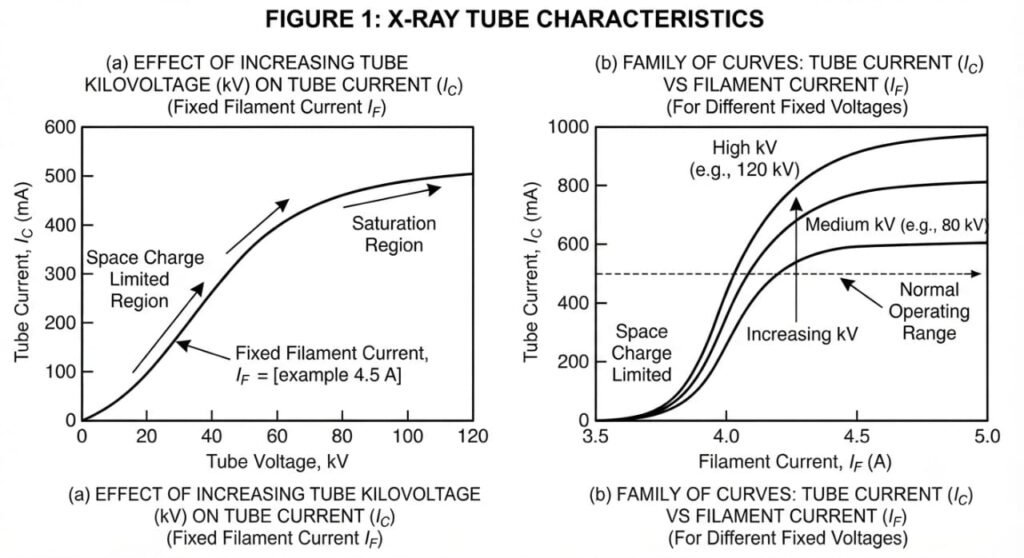
FIGURE 1
(a) The effect of increasing tube kilovoltage on the tube current for a fixed filament current. (b) A family of curves relating tube current to filament current for different applied voltages.
If the voltage is increased at fixed filament current, the tube current will change as shown in (Figure 1 a).
At low voltages, the tube current increases as the kV is increased because more and more electrons from the space charge around the cathode are being attracted to the anode. In theory, the tube current should plateau when the voltage is large enough to attract all electrons to the anode. In practice there is always a cloud of electrons (the space charge) around the cathode and as the potential difference is increased, a few more electrons are attracted to the anode. The result is that, as the tube kV is increased, the maximum tube current attainable also increases. Hence a typical family of curves relating tube current to filament current might be as in (Figure 1b). Modern X-ray tubes contain several compensating circuits one of which stabilises the tube current against the effect of changes in voltage.
Generator Power-
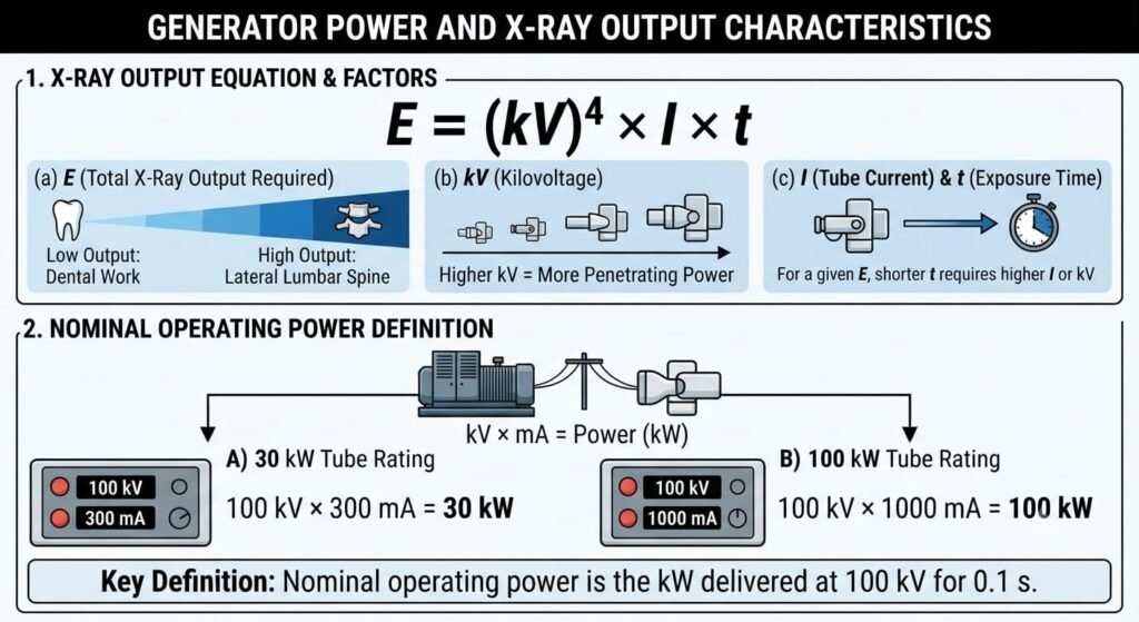
The relationship between the total output of X-rays required for a successful radiograph (E) and the exposure settings of kilovoltage (kV), current (I) and time (t) can be expressed approximately in the form
E = (kV)4 × I × t
The required value of E will depend on the body parts being radiographed—for example, low for dental work, high for lateral lumbar spine. However, the required power in the generator (kV × mA) will depend also on t since short exposures for a given E will require higher kV and/or mA values. The nominal operating power is specified as the kW that can be delivered at 100 kV for 0.1 s. Thus a 30 kW tube allows 300 mA, a 100 kW tube allows 1000 mA. Typical maximum powers for different applications are shown in (Table ).
Thermal Rating—Considerations at Short Exposures-
When electrons strike the anode of a diagnostic tube, 99% of their energy is converted into heat. If this heat cannot be adequately dissipated, the anode temperature may quickly rise to a value at which damage occurs due to excessive evaporation, or the anode may melt which is even worse. The amount of heat the anode can absorb before this happens is governed by its thermal rating.
Exposure times between 0.02 s and 10 s are, somewhat arbitrarily, regarded as short exposures. The primary thermal consideration is that the area over which the electrons strike the anode should not overheat, sometimes referred to as short-term loadability. This is achieved by dissipating the heat over the anode surface as much as possible. The factors that determine heat dissipation will now be considered.
Effect of Cooling-
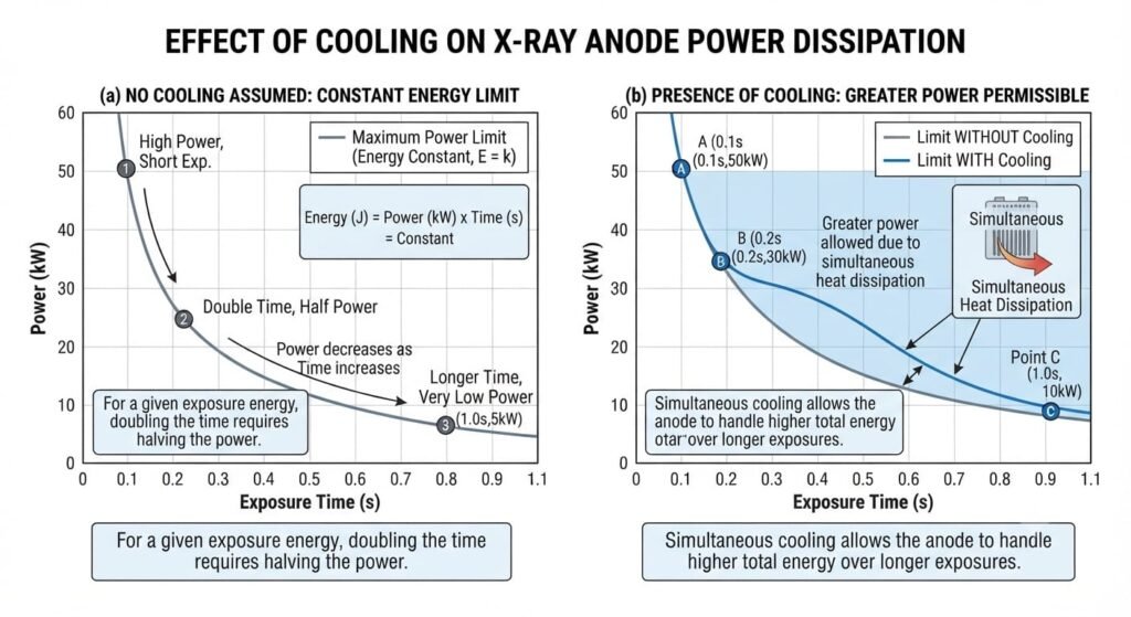
It is important to appreciate that when the maximum heat capacity of a system is reached, any attempt to achieve acceptable exposure factors by increasing the exposure time is dependent on the fact that during a protracted exposure some cooling of the anode occurs. Consider the extreme case of a tube operating at its anode thermal rating limit for a given exposure. If the exposure time is doubled in an attempt to increase film blackening then, in the absence of cooling, the tube current must be halved. This is because at a given kVp the energy deposited in the anode is directly proportional to the product of the current and the period of exposure. However, in the presence of cooling, longer exposure times do permit greater power dissipation as shown in (Figure 2).
Target Spot Size-
For fixed kVp and exposure time, the maximum permitted current increases with target spot size because the heat is absorbed over a larger area. For very small spots (~0.3 mm) the maximum current is approximately proportional to the area of the spot since this determines the volume in which heat is generated. For larger spots (~2 mm) the maximum current is more nearly proportional to the perimeter of the spot since the rate at which heat is conducted away becomes the most important consideration.
The larger focal spot, although allowing short exposure times, increases geometricalunsharpness .
Anode Design-
The main features that determine the instantaneous rating of a rotating anode are
• Its radius, which will determine the circumference of the circle on which the electrons fall
• Its rate of rotation
• The anode angle
• The focal spot size
The last two are closely related since the critical factor for heating is the area of the electron bombardment spot. For the same electron bombardment area a large angle anode will give a large focal spot, a small anode angle will give a small spot. Rather old rating curves showing the maximum permissible tube current for different exposure times for anodes of different design are shown in (Figure 3). A small anode angle and rapid rotation give the highest rating but note that the differences between the curves become progressively less as the exposure time is extended.
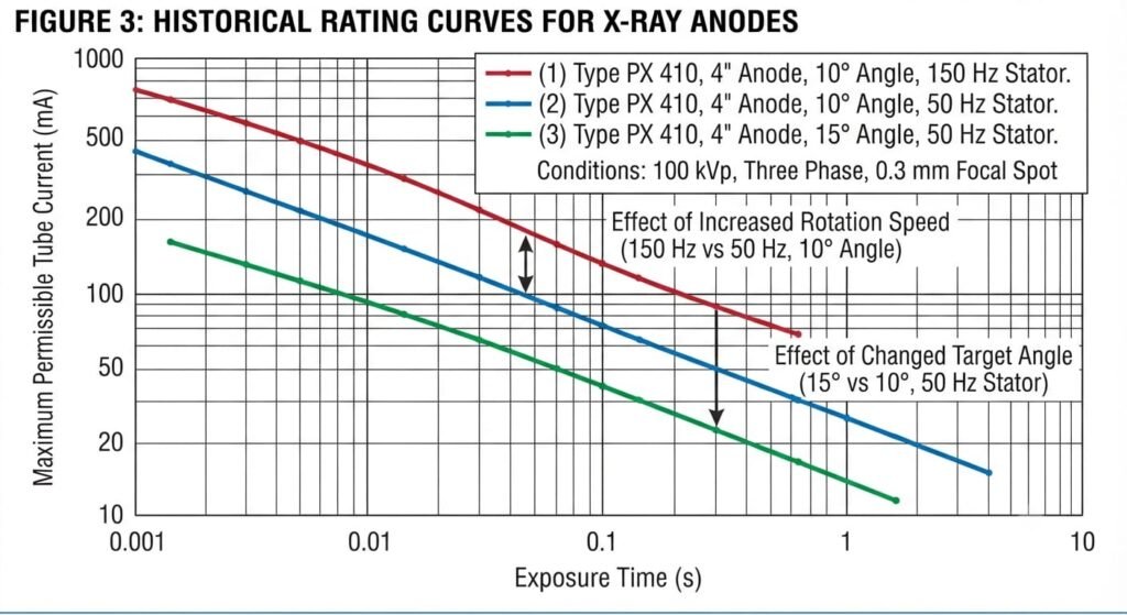
FIGURE 3
Historical rating curves showing the maximum permissible tube current at different exposure times for anodes of different design. Each tube is operating at 100 kVp three phase with a 0.3 mm focal spot. (1) Type PX 410 4 inch diameter anode with a 10° target angle and 150 Hz stator. (2) Type PX 410 4 inch diameter anode with a 10° target angle and 50 Hz stator. (3) Type PX 410 4 inch diameter anode with a 15° target angle and 50 Hz stator. Curves (1) and (2) show the effect of increasing the speed of rotation of the anode. Curves (2) and (3) show the effect of changing the target angle.
Note that
1. For the first complete rotation of the anode surface electrons are falling on unheated metal. For an anode rotation frequency of 50 Hz (the mains supply) one rotation requires 0.2 s so for even shorter exposures electrons fall on only part of the target length and the maximum tube current is independent of exposure time. The maximum permissible tube current for a stationary anode operating under similar conditions would be much lower.
2. For these old X-ray tubes the permitted tube current was very low .
Tube Kilovoltage-
As the kVp increases, the maximum permissible tube current for a fixed exposure time decreases (Figure 2.25). This is self-evident if a given power dissipation is not to be exceeded. Such a rating chart may be used to determine if a given set of exposure conditions is admissible with a particular piece of equipment. For example, is an exposure of 400 mA at 70 kVp for 0.2 s allowed? Reference to (Figure 4) shows that the maximum permissible exposure time for 400 mA at 70 kVp is about 1.0 s so the required conditions can be met.
Note that for very long exposures the product kVp × mA × time is converging to the same value for all curves and the heat storage capacity of the anode then becomes the limiting factor .
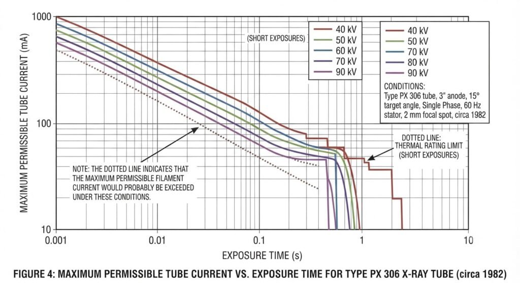
FIGURE 4
Maximum permissible tube current as a function of exposure time for various tube kilovoltages for a rotating anode. Type PX 306 tube with a 3 inch diameter anode, 15° target angle operating on a single phase with a 60 Hz stator and a 2 mm focal spot—circa 1982. Note: the dotted line indicates that the maximum permissible filament current would probably be exceeded under these conditions.
Full Wave Rectified and Three Phase Supplies-
When full wave rectified and three phase supply rating charts are compared at the same kVp, all other features of anode design being kept constant, the curves actually cross (Figure 5). For very short exposures higher currents can be used with a three phase than with a single phase supply, but the converse holds at longer exposures.
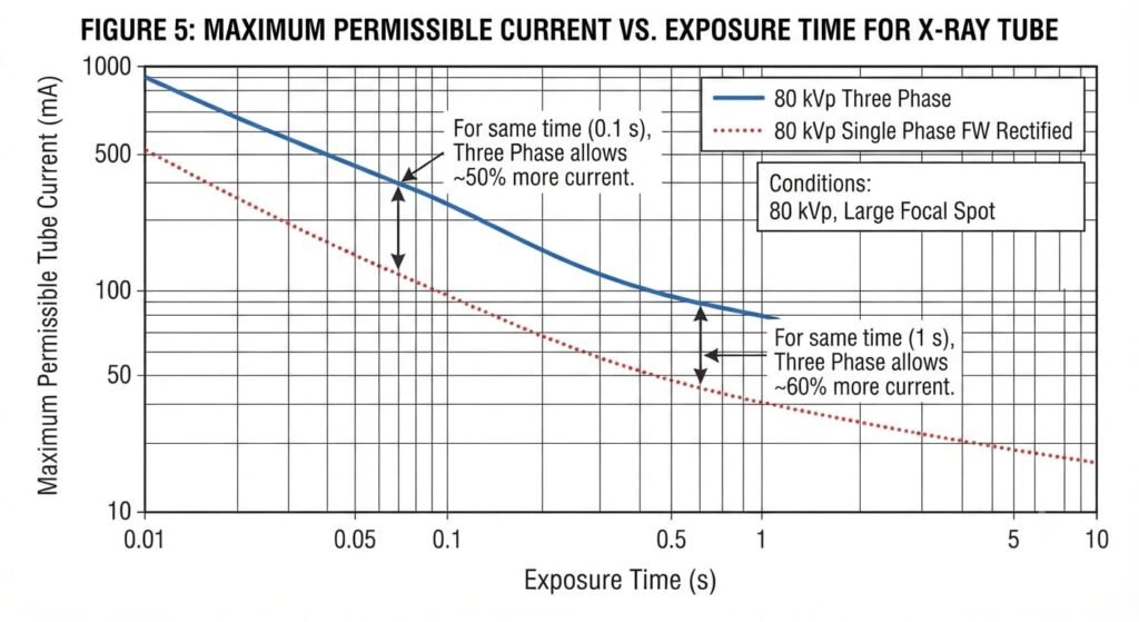
FIGURE 5
Maximum permissible current as a function of exposure time for 80 kVp single phase full wave rectified (dotted line) and 80 kVp three phase supplies (solid line).
To understand why this is so, consider the voltage and current waveforms for two tubes with the same kVp and mA settings (Figure 6). Note:
1. The current does not follow the voltage in the full wave rectified tube. As soon as the potential difference is sufficient to attract all the thermionically emitted electrons to the anode, the current remains approximately constant.
2. The three phase current remains essentially constant throughout.
3. The peak value of the current must be higher for the full wave rectified tube than for the three phase tube, if the average values as shown on the meter are to be equal.
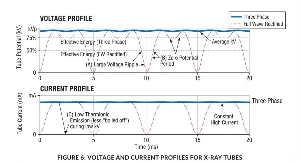
FIGURE 6
Voltage and current profiles for two tubes with the same kVp and mA settings but with three phase (solid line) or full wave rectified (dotted line) supplies.
Overcoming Short Exposure Rating Limits-
If a desired combination of kVp, mA, time and focal spot size is unattainable owing to rating limits, several things can be done, although all may degrade the image in some way. Increasing the focal spot size or the time of exposure has already been mentioned. The other possibility is to increase the kVp. At first inspection, this appears to give no benefit. Suppose the rating limit has been reached and the kVp is increased by 10%. The current will have to be reduced by 10% otherwise the total power dissipated as heat will increase.
The gain from increasing the kVp appears to be negated by a loss due to reduced mA. However, although X-ray output will fall by 10% as a result of reducing mA, it will increase by about 20% as a result of the 10% increase in kVp . Furthermore, X-ray transmission through the patient is better at the higher kVp and, in the diagnostic range, if film is the receptor, film sensitivity increases with kVp. Thus film blackening, which is ultimately the relevant criterion, is increased about 40% by the 10% increase in kVp and reduced by only about 10% due to reduction in mA, yielding a net positive gain. Some image degradation may occur as a result of loss of contrast at the higher kVp but patient dose would be reduced because there is less attenuation of X-rays in the body.
The most effective way to overcome short exposure rating limits, in the longer term, is by improved anode design. Especially in X-ray CT, the combined requirements for quick scanning sequences, dynamic serial studies and spiral CT have necessitated a high tube current being maintained for several seconds. Some interventional procedures, for example, sequential images of blood vessels where the blood flow is very rapid, also put severe demands on the anode.
An important design improvement was the introduction of anodes mounted on spiral groove bearings with a liquid metal alloy as lubricant . In addition to allowing the anode to rotate all day once power is applied to the unit, this design permits good thermal contact so a significant amount of heat may be lost by conduction and the load bearing is greater allowing an anode of greater diameter to be used.
Multiple or Prolonged Exposures-
If too many exposures are taken in a limited period of time, the tube may overheat for three different reasons:
1. The surface of the target can be overheated by repeated exposures before the surface heat has time to dissipate into the body of the anode.
2. The entire anode can be overheated by repeating exposures before the heat in the anode has had time to radiate into the surrounding oil and tube housing.
3. The tube housing can be overheated by making too many exposures before the tube shield has had time to lose its heat to the surrounding air.
The second and third problems can also arise during continuous fluoroscopy. Although tube currents are now low, 1–5 mA, compared to 500 mA or more in radiography, exposure times can be very long. The surface of the target will not overheat but heat dissipation from the entire anode or tube housing may still require consideration.
The heat capacity of the total system, or of parts of the system, is sometimes expressed in heat units (HU). By definition, 1.4 HU are generated when 1 J of energy is dissipated.
The basis of this definition can be understood for a full wave rectified supply
HU = 1.4 × energy
= 1.4 × root mean square (rms) kV × average mA × s
But
rms kV = 0.71 × kVp
Hence
HU = kVp × mA × s
Thus the HUs generated in an exposure are just the product of (voltage) × (current) × (time) shown on the X-ray control panel, so the introduction of the HU was very convenient for single phase generators.
Unfortunately, this simple logic does not hold for modern generators. The mean kV is now much higher, perhaps 0.95 kVp or better, so
HU = 1.4 × 0.95 kVp × mA × s = 1.35 × kVp × mA × s
Hence for three phase supply the product of kVp and mAs as shown on the meters must be multiplied by 1.35 to obtain the heat units generated. With the near universal use of three phase and high frequency generators, joules are becoming the preferred unit.
The rating charts already discussed may be used to check that the surface of the target will not overheat during repeat exposures. This cannot occur provided that the total heat units of a series of exposures made in rapid sequence does not exceed the heat units permissible, as deduced from the radiographic rating chart, for a single exposure of equivalent total exposure duration.
When the time interval between individual exposures exceeds 20 s there is no danger of focal track overheating. The number and frequency of exposures is now limited either by the anode or by the tube heat storage capacity. A typical set of anode thermal characteristic curves is shown in (Figure 7). Two types of curve are illustrated:
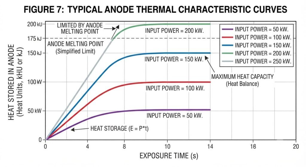
FIGURE 7 Typical anode thermal characteristic curves, showing the heat stored in the anode as a function of time for different input powers.
1. Input curves showing the heat stored in the anode after a specified, long period of exposure. Also shown, dotted, is the line for 700 watt input power in the absence of cooling. This line is a tangent to the curve at zero time since the anode is initially cold and loses no heat. At constant kVp the initial slope is proportional to the current. As the anode temperature increases, the anode starts to lose heat and the curve is no longer linear.
2. A cooling curve showing the heat stored in the anode after a specified period of cooling. Note that if the heat stored in the anode after exposure is only 120 kJ, the same cooling curve may be used but the point A must be taken as t = 0.
Two other characteristics of the anode are important. First, the maximum anode heat storage capacity, which is 200 kJ here, must be known. For low screening currents, the heat stored in the anode is always well below its heat limit, but for higher input power the maximum heat capacity is reached and screening must stop.
The second characteristic is the maximum anode cooling rate. This is the rate at which the anode will dissipate heat when near its maximum temperature (800 watts) and gives a measure of the maximum current, for given a kVp, at which the tube can operate continuously.
Note that under typical modern screening conditions, say 2 mA at 80 kVp, the rate of heat production is only 2 × 10–3 × 80 × 103 = 160 W.
During screening, or a combination of short exposures and screening, the maximum anode heat storage capacity must not be exceeded. Exercises in the use of this rating chart are given at the end of this chapter. Note that with the increased use of microprocessors to control X-ray output, the system will not allow the operator to make an exposure that might exceed a rating limit.
When the total time for a series of exposures exceeds the time covered by the anode thermal characteristic chart, a tube shield cooling chart must be consulted. This is similar to the anode chart except that the cooling time will extend (typically) to 100 min and the maximum tube shield storage capacity in some modern units may be as high as 4 × 10⁶ J.
Note that cooling of the housing can be enhanced with a heat exchanger. For example, by pumping oil or water through a set of tubes in the housing the time taken for the housing to lose 90% of its heat might be reduced by 50%.
As a final comment on thermal rating, it is worth noting that a significant amount of power is required to set the anode rotating and this is also dissipated eventually as heat. In a busy accident department taking many short exposures in quick succession, three times as much heat may arise from this source as from the X-ray exposures themselves.
Falling Load Generators-
One way to keep exposure times as short as possible for AEC exposures, without exceeding rating limits, is to use the falling load principle. This method of operation uses the fact that the rate of heat loss from the anode is greatest when the anode is at its maximum working temperature, so the current through the tube is kept as high as possible without this maximum temperature being exceeded. If the tube current is high for the initial part of the exposure while the anode is cold, but reduced during the exposure, the same mAs can be achieved in a shorter time than with constant current. This is illustrated in (Figure 8).
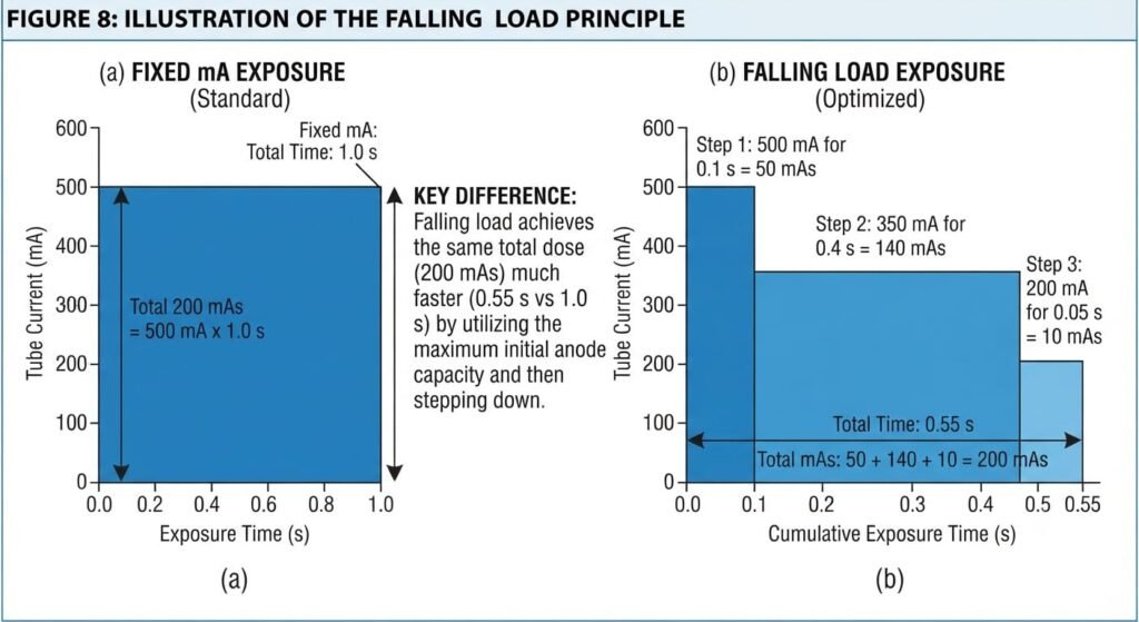
FIGURE 8
Illustration of the falling load principle. To achieve 200 mAs at a fixed mA requires a one second exposure. Using the falling load principle, the tube can operate at 500 mA for 0.1 s = 50 mAs, then drop to 350 mA for a further 0.4 s = 140 mAs, and finally to 200 mA for 0.05 s = 10 mAs, a total of 200 mAs in only 0.55 s.
The anode temperature is monitored and if it reaches the maximum allowed, a motor driven rheostat introduces an extra resistance into the filament circuit thereby reducing the tube current in a step-wise manner. Because the transformer is not ideal, this lowering of tube current causes an increase in the kVp, and this has to be compensated for by increasing the resistance in the primary circuit in the transformer. The exposure must be controlled using a meter calibrated in milliampere seconds or terminated using a phototimer for AEC (see Section 2.3.6). Note, however, that the falling load generator will be of little value for short exposure times (say 0.4 s) because there will be insufficient time for the current to fall through many steps. Also there is wear on the tube at high current so lifetime is shortened by falling load operation. Thus a falling load generator might be a possibility for a busy orthopaedic clinic examining spines with heavy milliampsecond loadings and long exposure times. For chest work it would be useless.
Safety Interlocks-
These are provided to ensure that rating limits are not exceeded on short exposures. If a combination of kVp, mA, exposure time and spot size is selected that would cause anode overheating, a ‘tube overload’ warning light will appear and the tube cannot be energised.
During multiple exposures a photoelectric cell may be used to sample radiant heat from the anode and thereby determine when the temperature of the anode disc has reached a maximum safe value. A visual or audible warning is then triggered. In modern systems the tube loading is under computer control. Anode temperature is continuously calculated from a knowledge of heat input and cooling characteristics. When the rating limit is reached, generator output is automatically reduced.
X-ray Tube Lifetime-
The life of an X-ray tube can be extended by taking steps to avoid thermal stress and other problems associated with heating. For example, the anode is very brittle when cold and if a high current is used in this condition, deep cracks may develop. Thus at the start of operations several exposures at approximately 75 kVp and 400 mAs (200 mA for 2 s) should be made at 1 min intervals. Ideally, if the generator is idle for periods exceeding 30 min, the process should be repeated.
Keeping the ‘prepare’ time to a minimum will reduce filament evaporation onto the surface of the tube and also bearing wear in the rotating anode. The generator should be switched off when not in use. The tube should be operated well below its rating limits whenever possible.