Protective Housing & Cooling System in X-Ray Tube: Everything You Need to Know

The generation of diagnostic X-rays is one of the most energy-inefficient processes in applied physics. During exposure, approximately 99% of the kinetic energy of bombarding electrons is converted directly into waste thermal energy, with less than 1% converted into useful X-ray photons.
In high-throughput clinical environments—such as Computed Tomography (CT) or Interventional Angiography—anode temperatures frequently exceed 2,000°C, accompanied by input voltages ranging between 25 kV and 150 kV. To prevent physical destruction, electrical arcing, and dangerous radiation exposure, the glass/metal vacuum tube insert must be housed within a specialized, multi-layered protective structure integrated with an active thermal management system.
1. Structural and Safety Functions of the Protective Housing
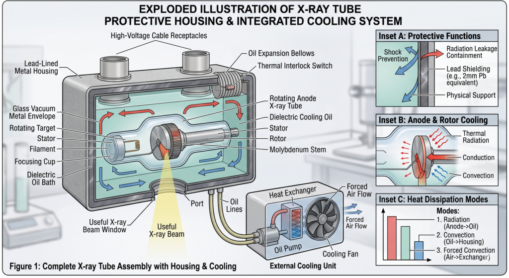
The protective housing (often referred to as the tube housing assembly) is an engineered, heavy-duty enclosure—typically constructed of cast aluminum or steel and lined with lead—designed to fulfill three critical physical and operational safety functions:
A. Radiation Shielding & Leakage Reduction
X-rays are generated isotropically (in all directions) at the focal spot. While the primary diagnostic beam is directed through a designated low-attenuation port/window (often made of beryllium or thin glass), all off-axis radiation must be contained.
- Lead Lining: The inner walls of the metallic housing are lined with sheet lead (typically equivalent to 2 mm of pure lead (Pb)).
- Regulatory Compliance: International radiological safety standards (IEC and FDA regulations) mandate that leakage radiation escaping through the housing must not exceed 1 mGy/hr (100 mR/hr) at a distance of 1 meter when operated at maximum continuous power settings.
B. High-Voltage Electrical Isolation
Operating an X-ray tube requires massive potential differences (25 to 150 kVp) across the cathode-anode gap. At these extreme voltages, atmospheric air would instantly break down, resulting in continuous arc discharges.
- Dielectric Oil Bath: The space between the vacuum tube insert and the outer protective housing is filled with highly refined, high-dielectric mineral oil. This oil provides high electrical insulation, preventing arcover between the internal high-voltage terminals and the grounded outer shell.
- Receptacles: Shielded high-voltage cable receptacles route power into the tube without compromising the dielectric seal.
C. Mechanical Support & Vacuum Integrity Protection
The glass or metal envelope containing the cathode and anode operates under an ultra-high vacuum (∼10−6 to 10−8 Torr) to prevent electron scattering against gas molecules.
- Vibration Dampening: The protective housing mechanically suspends the fragile vacuum envelope, isolating it from physical shocks, mechanical vibrations, and g-forces caused by gantry rotation in modern CT scanners.
- Structural Framing: It serves as the physical mounting interface for collimator assemblies, filters, and positioning arms.
2. Multi-Level Thermal Management and Heat Dissipation
Managing thermal energy in an X-ray tube requires handling heat across three sequential physical zones: within the target, across the vacuum, and outside the housing.
[ Focal Spot ] ---> (Conduction/Radiation) ---> [ Anode Disc ]
                                                     |
                                            (Thermal Radiation)
                                                     v
[ Ambient Air ] <--- (Forced Air/Fans) <--- [ Dielectric Oil Bath ]
Zone 1: Heat Absorption at the Anode (Focal Track Level)
To prevent localized melting at the focal spot:
- Rotating Anodes: The anode disc rotates at speeds between 3,000 RPM (standard) and 10,000 RPM (high-speed). This spreads the electron beam’s energy over a circular track rather than a single static point, increasing the effective thermal area by up to 200 times.
- Target Material Composition: Targets are composed of a Tungsten-Rhenium alloy (high melting point of ∼3,422∘C and high atomic number Z=74) bonded to a thick backing of Molybdenum and Graphite. Graphite acts as a massive thermal reservoir due to its high specific heat capacity.
- Molybdenum Stem: The target disc is attached to the rotor motor via a narrow Molybdenum stem. Because Molybdenum has low thermal conductivity, it acts as a thermal barrier, limiting heat conduction down the shaft to protect the precision steel/ceramic ball bearings.
Zone 2: Heat Transport Across the Vacuum Barrier
Because heat cannot travel via convection or conduction through a vacuum, heat leaves the rotating target assembly primarily through two methods:
- Infrared Radiation (Primary): The white-hot anode disc radiates thermal energy across the vacuum gap directly onto the inner surface of the glass/metal vacuum envelope.
- Bearing Conduction (Secondary): A small fraction of heat travels down the stem into the rotor shaft and bearing assembly. Advanced tubes use liquid metal (Gallium-Indium-Tin alloy) bearings to improve conduction without physical wear.
Zone 3: Dissipation from Housing to Environment
Once thermal energy reaches the vacuum envelope, the cooling system surrounding the envelope takes over:
- Convection in the Dielectric Oil Bath: The oil directly contacts the outer surface of the hot glass/metal envelope. As the oil heats up, natural or pump-driven convection carries it away from the tube body toward the outer housing walls.
- Active Oil-to-Air Heat Exchangers: In high-workload systems, an internal motor pumps hot dielectric oil through an external radiator (heat exchanger). High-velocity cooling fans blow ambient room air across the radiator fins to rapidly drop the oil temperature.
- Thermal Expansion Bellows & Safety Interlocks: As the dielectric oil heats up, it expands in volume. The protective housing incorporates a flexible bellows diaphragm. If the oil temperature rises above safe operating limits (typically around 75∘C−80∘C), the expanding oil depresses a microswitch (thermal interlock), instantly tripping the system to disable further exposures until the assembly cools down.
Summary of System Components & Engineering Functions
| Component | Physical Material | Primary Function |
|---|---|---|
| Lead Shielding | Sheet Lead (2 mm Pb eq.) | Blocks off-axis radiation; limits leakage to <1 mGy/hr at 1 m. |
| Outer Enclosure | Cast Aluminum / Steel | Provides mechanical mounting, structural rigidity, and physical protection. |
| Dielectric Oil | Hydrocarbon Mineral Oil | Delivers high-voltage electrical insulation and acts as a convective cooling medium. |
| Expansion Bellows | Flexible Metallic Membrane | Accommodates oil volume expansion; triggers the thermal safety microswitch. |
| Heat Exchanger | Copper Coils / Aluminum Fins | Transfers heat actively from circulating oil to ambient room air via forced fan draft. |
| Rotating Anode Target | Tungsten-Rhenium on Graphite | Withstands high thermal impact; rapidly radiates heat out to the vacuum envelope. |