

The anode assembly serves as the positive terminal inside a diagnostic X-ray tube. While the cathode assembly generates and shapes the incoming electron beam, the anode assembly acts as the target: receiving ultra-high-speed electrons, absorbing and dissipating the extreme thermal energy generated during collision, and converting electron kinetic energy into diagnostic X-ray photons through Bremsstrahlung and Characteristic radiation.
Because more than 99% of the kinetic energy carried by the incident electron beam is converted into heat—with less than 1% converted into usable X-rays—the material selection, structural layering, geometric angling, and heat-dissipation properties of the anode are the primary factors limiting an X-ray system’s power capacity, spatial resolution, and overall lifespan.
Structural Types: Stationary vs. Rotating Anodes
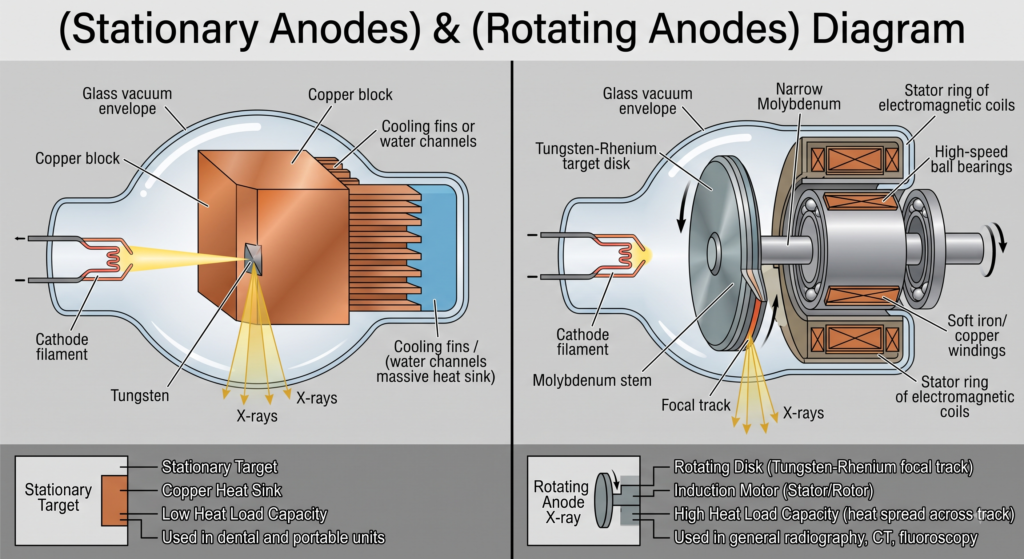
Depending on the mechanical output requirements of the imaging equipment, anode assemblies are built using one of two fundamental structural designs:
                            Anode Configurations
                                     │
         ┌───────────────────────────┴───────────────────────────┐
         ▼                                                       ▼
┌──────────────────┐                                   ┌──────────────────┐
│ Stationary Anode │                                   │  Rotating Anode  │
└────────┬─────────┘                                   └────────┬─────────┘
         │ Fixed Target Spot                                    │ Continuous Rotating Track
         ▼                                                      ▼
  [ Low Heat Load ]                                      [ High Heat Load ]
  Dental & Portable Units                                General Radiography & CT
1. Stationary Anodes
- Structure: Consists of a small block of tungsten embedded directly into a massive block of solid copper.
- Thermal Pathway: The heat generated at the small collision site conducts through the copper block into an external oil bath.
- Limitations: Because electrons hit the exact same spot continuously, heat builds up rapidly. Consequently, stationary anodes are strictly limited to low-output equipment such as intraoral dental units and lightweight portable X-ray devices.
2. Rotating Anodes
- Structure: Consists of a beveled, disc-shaped target mounted onto a central shaft assembly.
- Thermal Pathway: Instead of striking a fixed area, the electron beam impacts a continuously spinning ring—the focal track. Spreading the heat over a much larger surface area increases heat storage capacity by up to 1,000 times compared to stationary designs.
- Applications: Universal in general radiography, fluoroscopy, computed tomography (CT), and interventional suite equipment.
Core Components of the Anode Body
A modern rotating anode body is a multi-layered composite disk designed to handle severe thermal gradients, high mechanical stress, and intense radiation.
                   Target Disk Multi-Layer Cross-Section
                   ┌───────────────────────────────────┐
                   │  Tungsten-Rhenium Focal Track     │  <-- Impact Zone (High Z, High Melting Point)
                   ├───────────────────────────────────┤
                   │  Molybdenum Core Substructure     │  <-- Heat Distribution & Structural Support
                   ├───────────────────────────────────┤
                   │  Graphite Base Layer              │  <-- Thermal Sink & Reduced Inertial Mass
                   └─────────────────┬─────────────────┘
                                     │
                                     ▼
                   ┌───────────────────────────────────┐
                   │  Molybdenum Shaft / Stem          │  <-- Thermal Isolation Choke
                   └───────────────────────────────────┘
1. The Target Surface (Focal Track)
The active outer band where electrons collide is manufactured from a Tungsten-Rhenium alloy (90–95% Tungsten, 5–10% Rhenium).
- Tungsten (Z=74): Selected for its high atomic number, which increases X-ray production efficiency, and its exceptional melting point (3,422∘C), which withstands intense electron bombardments without melting.
- Rhenium Addition: Pure tungsten becomes brittle and cracks under repeated thermal expansion and contraction. Adding rhenium increases the elastic limit of the alloy, preventing the surface from thermal cracking, pitting, and crazing.
2. Substructure Layers (Molybdenum & Graphite)
Beneath the tungsten-rhenium surface lies a multi-layer backing designed to manage heat:
- Molybdenum Core: Molybdenum has a high melting point (2,623∘C) and lower density than tungsten, providing structural support while keeping the disk lighter.
- Graphite Backing Layer: High-capacity anodes feature a thick layer of graphite bonded to the underside of the disk. Graphite has a very high specific heat capacity, allowing it to act as a thermal reservoir that absorbs heat from the tungsten layer without adding excessive weight to the drive assembly.
3. The Molybdenum Shaft / Stem
The target disk is joined to the central mechanical assembly via a long, narrow molybdenum stem.
Because molybdenum is a poor thermal conductor compared to metals like copper, the narrow stem acts as a thermal neck or choke. It limits the rate at which heat transfers down from the glowing red disk (>1,000∘C) into internal supporting mechanical parts, protecting critical components from thermal seizure.
Specialized X-Ray Tube Anodes (Mammography, Dental, Fluoroscopy, & CT)
In general diagnostic radiography, x-ray tube anodes typically rely on tungsten-rhenium target tracks mounted on molybdenum or graphite bases. However, specialized medical imaging applications—such as Mammography, Dental Radiography, Fluoroscopy, and Computed Tomography (CT)—present unique physical, geometrical, and thermal demands.
To optimize image contrast, spatial resolution, and heat dissipation for each modality, engineers have designed specialized anode assemblies tailored to these specific clinical tasks.
1. Mammography X-Ray Tube Anodes
Mammography requires high-contrast imaging of soft tissues (fat, glandular tissue, and microcalcifications) with minimal radiation dose to the patient. Soft tissue contrast demands low-energy photon spectra (17 to 25 keV). Standard tungsten anodes produce x-rays at higher energies that pass through soft tissues without providing adequate contrast.
                           Mammography Anode
                                   │
         ┌─────────────────────────┴─────────────────────────┐
         ▼                                                   ▼
┌─────────────────┐                                 ┌─────────────────┐
│ Molybdenum (Mo) │                                 │  Rhodium (Rh)   │
│   (Z = 42)      │                                 │   (Z = 45)      │
└────────┬────────┘                                 └────────┬────────┘
         │ K-characteristic: 17.5 & 19.6 keV                 │ K-characteristic: 20.2 & 22.7 keV
         ▼                                                   ▼
[ Fatty & Medium Breasts ]                          [ Dense / Thick Breasts ]
Key Engineering Features:
- Target Materials:
- Molybdenum (Mo,Z=42): Produces K-characteristic x-rays at 17.5 keV and 19.6 keV. These energies sit within the absorption window for fatty and average-density breast tissue.
- Rhodium (Rh,Z=45): Used for dense breast tissue. Rhodium produces characteristic x-rays at 20.2 keV and 22.7 keV, providing a slightly harder beam that penetrates dense parenchymal tissue better than molybdenum without significantly increasing scatter.
- Dual-Track Anodes: Many modern systems utilize a rotating anode with dual target tracks (one molybdenum, one rhodium) that automatically switch based on compressed breast thickness.
- Micro-Focal Spots (0.1 mm to 0.3 mm): Magnification mammography demands small focal spots to resolve tiny microcalcifications (<0.1 mm) without geometric blur.
- Steeper Anode Angles (0∘ to 16∘): Combined with tilting the tube housing, a steeper anode angle allows for a wide coverage field while maintaining a small effective focal spot.
2. Dental X-Ray Tube Anodes
Dental imaging is divided into Intraoral Radiography (periapical/bitewing) and Extraoral Imaging (Panoramic/CBCT).
                            Dental Anodes
                                  │
         ┌────────────────────────┴────────────────────────┐
         ▼                                                 ▼
┌──────────────────┐                              ┌──────────────────┐
│ Stationary Anode │                              │  Rotating Anode  │
│  (Intraoral)     │                              │ (Panoramic/CBCT) │
└────────┬─────────┘                              └────────┬─────────┘
         │ Low Heat Loading                                │ High Thermal Capacity
         ▼                                                 ▼
[ Compact & Low-Power ]                           [ Continuous Scans ]
A. Intraoral Dental Anodes (Stationary Anodes)
- Design: Extremely compact, stationary anodes consisting of a small tungsten target disk embedded inside a massive copper block.
- Thermal Management: Because intraoral exposures are brief (0.01 to 0.5 seconds) with low tube currents (4 to 10 mA), heat load is minimal. Copper acts as a passive heat sink, conducting thermal energy away from the tungsten target without requiring a motor drive.
- Focal Spot: Small focal spots (0.4 mm to 0.7 mm) yield sharp detail of fine dental structures (enamel, dentin, periodontal ligament).
B. Panoramic & Cone-Beam CT (CBCT) Anodes
- Design: CBCT requires continuous exposures lasting 10 to 40 seconds as the gantry rotates around the patient’s head. These units utilize small-diameter rotating tungsten anodes to withstand sustained thermal loading while maintaining small focal spot sizes (0.2 mm to 0.5 mm).
3. Fluoroscopy & Interventional Suite Anodes
Fluoroscopy involves continuous, real-time imaging (e.g., barium studies, cardiac catheterization, angiography). The anode must support two operating modes: continuous low-current output (1 to 5 mA) and high-current radiographic exposures/pulsed fluoroscopy (100 to 1,000 mA).
                     Fluoroscopy Anode Architecture
                   ┌────────────────────────────────┐
                   │ High-Capacity Composite Disk   │
                   │ (Tungsten + Molybdenum + Graph)│
                   └───────────────┬────────────────┘
                                   │
                   ┌───────────────┴────────────────┐
                   │ Grid-Controlled Bias System    │
                   │ (Pulsed Mode: Fast On/Off)     │
                   └────────────────────────────────┘
Key Engineering Features:
- High Heat Storage Capacity Disk: Uses a heavy Graphite-backed composite disk (120 mm to 150 mm in diameter). Graphite acts as a thermal buffer, absorbing the continuous baseline heat generated during prolonged fluoroscopic runs.
- Grid-Controlled Target Switching: Pulsed fluoroscopy delivers brief pulses of radiation (e.g., 15 to 30 pulses per second) to reduce patient dose. Rather than pulsing high voltage across the transformer, a grid voltage on the focusing cup turns the electron beam on and off instantly without putting thermal shock on the anode.
- Liquid-Cooled Housing Circulation: Heat radiated from the large anode disk is absorbed by surrounding dielectric oil, which is actively pumped through an external heat exchanger or chiller.
4. Computed Tomography (CT) Anodes
Computed Tomography represents the most thermally demanding application in diagnostic imaging. CT tubes operate at high voltages (80 to 140 kVp) and high tube currents (200 to 1,000 mA), producing massive thermal loads (5 to 8 Mega Heat Units [MHU]) during fast continuous helical scans.
                          CT Anode Innovations
                                   │
         ┌─────────────────────────┼─────────────────────────┐
         ▼                         ▼                         ▼
┌──────────────────┐      ┌──────────────────┐      ┌──────────────────┐
│ Liquid Metal     │      │ Direct Oil-Cooled│      │ Flying Focal Spot│
│ Bearings (GalInst│      │ Anodes           │      │ (Electromagnetic)│
└────────┬─────────┘      └────────┬─────────┘      └────────┬─────────┘
         │ Continuous Heat         │ Direct Fluid            │ Doubles Spatial
         ▼ Conduct Through Bearing ▼ Conduction              ▼ Sampling Rate
 [ Eliminates Friction ]   [ Highest Heat Dissipation][ High Resolution ]
Key Engineering Features:
- Liquid Metal Bearings (GalInstan): Traditional ball bearings wear out rapidly at CT’s high temperatures and rotational speeds (10,000 RPM). Modern CT anodes use bearings lubricated with a liquid metal alloy (Gallium-Indium-Tin).
- Thermal Benefit: Provides a direct metallic thermal path, conducting heat straight from the spinning anode shaft out through the bearings (unlike ball bearings, which rely purely on radiant cooling).
- Direct Coolant / Rotating Envelope Tubes (e.g., Straton Tube): In advanced CT scanners, the entire tube envelope rotates along with the anode disk. The backside of the anode target is in direct contact with circulating oil, dissipating heat directly via conduction/convection rather than waiting for radiant thermal transfer.
- Flying Focal Spot (Electromagnetic Deflection): CT demands high image sharpness. Electromagnetic deflection coils rapidly wobble the electron beam back and forth on the anode target during gantry rotation, creating two alternating focal spots and doubling the spatial sampling rate without overheating the focal track.
Summary Comparison Matrix
| Imaging Modality | Anode Target Material | Structural Type | Primary Engineering Focus | Key Challenge Solved |
|---|---|---|---|---|
| Mammography | Molybdenum (Mo), Rhodium (Rh) | Small Rotating / Dual-Track | Low-energy characteristic x-rays (17−23 keV) | High soft-tissue contrast |
| Intraoral Dental | Tungsten (W) in Copper block | Stationary | Compact size, passive cooling | Simple, low-power intraoral imaging |
| Fluoroscopy | Tungsten-Rhenium (W-Re) on Graphite | Large Heavy Rotating | High continuous thermal storage | Sustained real-time imaging runs |
| CT Scanning | Tungsten-Rhenium on Moly/Graphite | Liquid Metal / Direct-Cooled Rotating | Extreme dissipation (>5 MHU), fast spin | Continuous high-power helical scanning |
Physical Dynamics and Geometrical Principles
1. The Line-Focus Principle
To achieve high spatial resolution in radiographs, the source of radiation must be as small as possible (approximating a point source). However, focusing high electron power onto a tiny physical area leads to instant target melting.
The Line-Focus Principle resolves this tradeoff by slanting the face of the anode target at a target angle (θ), typically between 6∘ and 20∘:
- Actual Focal Spot: The physical area on the target surface hit by the incoming electron stream.
- Effective Focal Spot: The projected area of the X-ray beam emerging vertically downward toward the patient and detector.
Effective Focal Spot Size=Actual Focal Spot Size×sin(θ)
By slanting the target, the actual focal spot remains large enough to spread out heat energy, while the projected effective focal spot appears small, preserving detail and spatial sharpness.
2. The Anode Heel Effect
Because X-ray photons are produced slightly beneath the surface of the tungsten target, photons emitted toward the anode side must pass through a thicker layer of target material than those emitted toward the cathode side.
       [ Cathode Side ]                          [ Anode Side ]
              │                                         │
              │                                     ┌───┴───┐
              │                                     │ Target│
              │                                     │ Slant │
              ▼                                     └───┬───┘
   (Shorter Path in Target)                  (Longer Path in Target)
              │                                         │
              ▼                                         ▼
   [ Higher X-Ray Intensity ]                [ Lower X-Ray Intensity ]
This self-absorption reduces the beam intensity on the anode side of the field:
- Radiation intensity on the cathode side is higher (≈105–120%).
- Radiation intensity on the anode side is lower (≈75–90%).
Clinical Application: Radiographers align the thicker body parts (such as the abdomen, pelvis, or femur) under the cathode side, and thinner anatomy under the anode side to produce balanced exposure across the image.
Heat Dissipation Mechanics
During high-powered exposures, the target track can reach temperatures above 1,500∘C to 2,000∘C. The anode dissipates this energy using three distinct heat transfer methods:
- Thermal Radiation: The primary cooling mechanism during exposure. The incandescent, glowing anode disk radiates heat energy outward via infrared radiation into the surrounding vacuum and oil bath.
- Thermal Conduction: Heat travels slowly up the narrow molybdenum stem from the high-temperature disk toward the cooler mounting assembly.
- Convection: Heat transferred to the surrounding oil bath is carried away from the tube envelope to the outer protective casing via liquid convection.
Anode Degradation & Failure Modes
Thermal stress and high electrical power make the anode one of the primary components prone to damage over time:
- Focal Track Pitting & Melting: Operating the tube beyond its single-exposure heat limits causes localized melting along the track. This creates pits and divots that scatter the X-ray beam, reducing radiation output efficiency.
- Thermal Stress Cracking: Exposing a cold anode to a high-power exposure without a proper warm-up sequence creates rapid thermal gradients, causing the target disk to warp or fracture.
- Target Imbalance: Surface wear, micro-cracking, or structural warping alters the rotational balance of the disk, leading to mechanical vibration during operation.
