
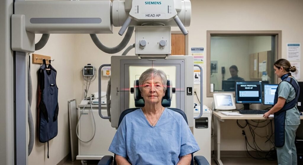
The Anteroposterior (AP) View of the Skull (0° AP Cranium) is a standard diagnostic projection used primarily to evaluate the anterior cranial vault, frontal bones, orbital margins, and cranial symmetry when a patient cannot assume the standard Posteroanterior (PA) position.
1. Clinical Indications & Contraindications
Detailed Indications:
- Major Head Trauma & Polytrauma: Detection of linear, comminuted, or depressed fractures of the frontal bone, parietal bones, or supraorbital ridges when the patient cannot be turned prone.
- Cervical Spine Clearance Protocol: Performed on polytrauma patients on a spinal board wearing a rigid cervical collar (C-collar) without manipulating the head or neck.
- Pediatric & Geriatric Assessments: Used for uncooperative children, bedridden patients, or elderly individuals with severe kyphosis who cannot lie prone or maintain the PA erect position.
- Pathological & Metabolic Bone Conditions:
- Evaluation of lytic or blastic lesions (e.g., Multiple Myeloma, metastatic disease, “salt-and-pepper” appearance in Hyperparathyroidism).
- Paget’s disease (osteitis deformans) showing cotton-wool appearance of the calvarium.
- Cranial osteomyelitis or fibrous dysplasia.
- Suture & Structural Assessment: Evaluation of premature closure of cranial sutures (craniosynostosis) and macrocephaly/microcephaly in pediatric cases.
- Intracranial Calcifications & Foreign Bodies: Localization of radio-opaque foreign bodies, metallic fragments, or calcifications within the pineal gland or choroid plexus.
- Post-Surgical Follow-up: Verification of craniotomy bone flap alignment, burr hole margins, or intracranial hardware/shunt placement.
Contraindications & Limitations:
- Unstabilized Cervical Spine Injury: Never forcefully flex, extend, or rotate the head to align reference lines (like OML) until the C-spine is cleared radiologically. The projection must be adapted using central ray tube angulation instead.
- Elective Non-Trauma Cases (Relative): For cooperative, ambulatory patients, the standard PA Skull projection is strongly indicated over the AP projection to reduce radiation exposure to the radiosensitive ocular lenses (radiation cataracts) and eliminate geometric magnification of the orbits.
- Severe Facial Bone Fractures (Stand-alone): AP 0° Skull is not optimal for isolated zygomatic arch, nasal bone, or blowout fractures due to superimposition of the petrous ridges over the orbits; specialized projections (Waters/Caldwell) or CT scans are indicated instead.
2. Technical Factors
| Parameter | Recommended Specification | Radiographic Rationale |
|---|---|---|
| Image Receptor (IR) | 24×30 cm (10×12 inches) | Longitudinal / Portrait orientation |
| Source-to-Image Distance (SID) | 100 to 115 cm (40 to 44 inches) | Standard geometry to balance sharpness and field size |
| Grid Ratio | 8:1 to 12:1 focused grid | High scatter cleanup from the dense cranium |
| Tube Potential (kVp) | 75−85 kVp | High penetration needed for dense petrous bones |
| mAs Range | 25−35 mAs | Calibrated based on cranial thickness or AEC center cell |
| Focal Spot | Small (0.6 mm) | Maximizes spatial detail of suture lines and hairline fractures |
| Shielding | Gonadal and thyroid lead shielding | Patient protection against secondary scatter |
| Breathing | Suspended respiration | Eliminates respiratory motion artifacts |
3. Step-by-Step Patient & Part Positioning
[ Central Ray: 0° ]
│
▼
(Glabella / Nasion)
───────┬───────
/ │
│ OML │ │ ◄── Orbitomeatal Line (Perpendicular to IR)
│ ───────┼──────── │
│ MSP / ◄── Mid-Sagittal Plane (Perpendicular to IR)
───────┴───────
[ Image Receptor ]
- Patient Preparation: Remove all radiopaque foreign objects from the head and neck region, including earrings, necklaces, hairpins, wigs, dentures, glasses, hearing aids, and dental prostheses.
- Basic Posture:
- Table/Recumbent: Place the patient supine on the radiographic table with arms resting by their sides and shoulders in the same transverse plane to avoid tilting.
- Erect/Upright: Seat or stand the patient facing the X-ray tube with the posterior aspect of the skull (occiput) touching the upright Bucky.
- Alignment of Reference Lines & Planes:
- Mid-Sagittal Plane (MSP): Align the MSP strictly perpendicular to the midline of the grid/table. Stand at the patient’s head to confirm the nose, philtrum, and chin are aligned without any left/right head rotation.
- Orbitomeatal Line (OML): Gently tuck the patient’s chin to bring the line connecting the outer canthus of the eye to the external auditory meatus (EAM) perpendicular to the plane of the IR.
- Interpupillary Line (IPL): Ensure the imaginary line connecting the pupils is strictly parallel to the plane of the IR; this confirms zero lateral tilt.
- Vertex Coverage: Ensure the top of the image receptor extends approximately 2 to 3 cm beyond the cranial vertex.
Positioning Adjustments for Trauma/Restricted Mobility:
- If the patient is immobilized in a rigid C-collar or has severe kyphosis and cannot achieve OML perpendicular:
- Align the Infraorbitomeatal Line (IOML) (infraorbital margin to EAM) perpendicular to the IR instead.
- Angle the Central Ray 3∘ to 5∘ Caudad to match the 7∘ anatomical angle difference between OML and IOML.
4. Central Ray (CR) & Collimation
- CR Angle: 0∘ (perpendicular to the image receptor and parallel to the OML).
- CR Entry Point: Directed straight to the Glabella (or mid-nasion level, roughly 2 cm superior to the nasofrontal junction).
- Collimation: Four-sided collimation adjusted strictly to the outer skin margins of the skull vault (vertex superiorly, mental protuberance/chin base inferiorly, and lateral skin edges).
5. Radiographic Anatomy & Quality Evaluation Criteria
- Petrous Ridge Superimposition: The petrous ridges of the temporal bones must completely fill the lower third to middle third of the orbits (the standard hallmark of true 0∘ OML alignment).
- Rotational Symmetry:
- Equal distance measured from the lateral cranial margin (inner and outer table) to the lateral orbital margins on both sides.
- The crista galli, nasal septum, and anterior nasal spine lie along the central anatomical midline.
- Absence of Lateral Tilt: Both orbital roofs and petrous ridges are at identical horizontal planes without asymmetry.
- Visualization: Complete calvarium including frontal bone, crista galli, frontal sinuses, ethmoid air cells, and coronal/sagittal sutures with distinct bony detail and no motion blur.

The Posteroanterior (PA) View of the Skull (0° Central Ray) is the fundamental baseline projection for cranial radiography. Unlike the modified Caldwell projection (which uses a 15⁰ caudal tilt), the 0° PA baseline directs the X-ray beam perpendicular to the image receptor, providing an un-distorted view of the frontal bone, internal auditory canals, and symmetrical calvarial structures while minimizing radiation exposure to the eyes.
1. Clinical Indications & Contraindications
Detailed Indications:
- Frontal Bone Pathologies & Trauma: Detection of linear, depressed, or stellate fractures of the frontal bone, supraorbital margins, and frontal air sinuses.
- Calvarial Symmetry & Suture Analysis: Evaluation of the sagittal suture, coronal sutures, and craniosynostosis (premature suture fusion) in pediatric/adolescent cases.
- Neoplastic & Destructive Bone Lesions: Assessment of osteolytic or osteoblastic lesions, Multiple Myeloma (“punched-out” lytic lesions), and metastases in the cranial vault.
- Metabolic & Chronic Bone Diseases: Radiographic diagnosis of Paget’s disease (osteitis deformans), fibrous dysplasia, hyperparathyroidism (“salt-and-pepper” appearance), and hyperostosis frontalis interna.
- Intracranial Calcifications & Foreign Bodies: Identification and localization of radiopaque foreign materials, pineal gland calcifications, choroid plexus calcifications, and falx cerebri calcification.
- Evaluation of Crista Galli & Ethmoid Sinuses: Clear visualization of the perpendicular plate of the ethmoid, crista galli, and superior nasal septum.
Contraindications & Limitations:
- Unstable Cervical Spine Trauma: Absolute contraindication for prone or erect positioning. If a C-spine injury is suspected, never turn the patient face down or manipulate the neck; perform an AP 0° Supine / Trauma AP instead.
- Severe Facial / Nasal Trauma: Patients with active epistaxis, crushed facial bones, or open nasal fractures should not have their forehead and nose pressed against the bucky surface.
- Uncooperative or Bedridden Patients: Severely kyphotic elderly patients or pediatric patients who cannot hold the forehead-nose position should be positioned AP.
- Inferior Orbital Rim Evaluation (Limitation): Because the central ray is 0⁰, the dense petrous ridges completely superimpose over the orbits, obscuring the inferior orbital rims and orbital floor (a 15⁰ Caldwell or 37⁰ Waters view is needed for orbital floor/sinus assessment).
2. Technical Factors
| Parameter | Recommended Specification | Radiographic Rationale |
| Image Receptor (IR) | 24 × 30 cm (10″ × 12″) | Longitudinal / Portrait orientation |
| Source-to-Image Distance (SID) | 100 to 115 cm (40 to 44 inches) | Maintains geometric resolution and controls beam divergence |
| Grid Ratio | 8:1 to 12:1 focused grid | Essential to absorb high amounts of scattered radiation |
| Tube Potential (kVp) | 75 – 85 kVp | High penetration required to pass through dense occipital and petrous bones |
| mAs Range | 25 – 35 mAs | Calibrated based on cranial thickness; center AEC cell active |
| Focal Spot | Small (0.6 mm) | Maximizes spatial detail of thin suture lines and fracture margins |
| Breathing | Suspended respiration | Eliminates respiratory and voluntary motion blur |
3. Step-by-Step Patient & Part Positioning
[ Image Receptor ]
───────┬───────
/ MSP │ OML ◄── Forehead & Nose touching IR
│ ───────┼──────── │ ◄── Orbitomeatal Line (Perpendicular to IR)
│ │ │
│ / ◄── Mid-Sagittal Plane (Perpendicular to IR)
───────┴───────
▲
│
[ Central Ray: 0° ]
(Exits at Glabella)
- Patient Preparation: Remove all radiopaque accessories (hairpins, metallic clips, earrings, wigs, spectacles, dentures, hearing aids, and dental plates).
- General Stance:
- Erect (Preferred): Seated or standing facing the vertical Bucky. This is more comfortable and prevents lateral body rotation.
- Prone (Alternative): Patient lies prone on the radiographic table with arms resting comfortably near the shoulders for stabilization.
- Alignment of Reference Lines & Contact Points:
- Forehead & Nose Contact: Rest the patient’s forehead and tip of the nose firmly against the table or vertical Bucky surface.
- Orbitomeatal Line (OML): Adjust head flexion/extension so the OML is strictly perpendicular to the plane of the image receptor.
- Mid-Sagittal Plane (MSP): Align the MSP perpendicular to the midline of the grid/bucky. Stand directly behind the patient to check that the head is not rotated to the left or right.
- Interpupillary Line (IPL): Ensure the IPL is strictly parallel to the plane of the IR (no lateral head tilt).
4. Central Ray (CR) & Collimation
- CR Angle: 0⁰ (perpendicular to the image receptor and parallel to the OML).
- CR Alignment / Exit Point: Directed horizontally (or vertically if prone) to exit at the Glabella (or mid-nasion level).
- Collimation: Four-sided collimation adjusted to the outer skin margins of the skull vault (vertex superiorly, chin base inferiorly, and lateral outer calvarial borders).
5. Key Differences: 0° PA Baseline vs. 15° PA Caldwell vs. 0° AP
| Feature | 0° PA Baseline Skull | 15° PA Caldwell View | 0° AP Skull View |
| Central Ray Angle | 0° (Perpendicular) | 15° Caudad | 0° (Perpendicular) |
| Petrous Ridge Position | Completely fills the orbits (lower 1/3 to middle) | Projected into the lower 1/3 or below orbits | Completely fills the orbits |
| Primary Region Shown | Frontal bone, calvarium, crista galli | Orbital rims, frontal & anterior ethmoid sinuses | Frontal bone & orbits (magnified) |
| Lens Radiation Dose | Minimal (eyes close to IR, away from tube) | Minimal | High (direct exposure to ocular lenses) |
| Orbital Magnification | None / Minimized (Low OID) | Minimized | Increased (Higher OID) |
6. Radiographic Anatomy & Quality Evaluation Criteria
3. Lateral Projection of the Skull (Right / Left Lateral Cranium)

The Lateral View of the Skull is a foundational projection included in almost all standard cranial series. It evaluates the lateral calvarium, the anterior/middle/posterior cranial fossae, the sella turcica in profile, and the relationship between the inner and outer cortical tables.
1. Clinical Indications & Contraindications
Detailed Indications:
- Cranial Vault & Base Trauma: Detection of linear, depressed, or comminuted fractures of the parietal, temporal, frontal, or occipital bones.
- Sella Turcica Pathologies: Assessment of sellar enlargement, erosion, or destruction due to pituitary adenomas, craniopharyngiomas, or “Empty Sella” syndrome.
- Intracranial Air & Fluid Levels (Cross-Table Lateral):
- Sphenoid sinus air-fluid levels indicative of a basilar skull fracture and cerebrospinal fluid (CSF) leakage.
- Pneumocephalus (intracranial air collection) following traumatic dural tears.
- Neoplastic & Osteolytic Lesions: Evaluation of “punched-out” lytic lesions in Multiple Myeloma, osteolytic metastases, eosinophilic granuloma, and epidermoid cysts.
- Metabolic & Bone Remodeling Diseases: Diagnosis of Paget’s disease (cotton-wool appearance, basilar invagination), fibrous dysplasia, hyperparathyroidism, and osteopetrosis.
- Pediatric Assessment & Suture Alignment: Evaluation of coronal, squamosal, and lambdoid sutures; detection of scaphocephaly, oxycephaly, or other craniosynostoses.
- Vascular & Normal Anatomical Calcifications: Identification of middle meningeal artery grooves, pacchionian (arachnoid) granulations, pineal gland calcification, and choroid plexus calcification.
Contraindications & Limitations:
- Unstable Cervical Spine Trauma (Standard Position): Patients with suspected or unconfirmed C-spine injuries must not have their heads turned or rotated into a standard lateral position. A Cross-Table (Horizontal Beam) Lateral must be performed in the true supine position with no neck movement.
- Bilateral Superimposition (Inherent Limitation): Left and right cranial structures superimpose over each other. Accurate localization of a small cortical lesion to a specific side often requires an orthogonal AP/PA view or tangential projections.
2. Technical Factors
| Parameter | Recommended Specification | Radiographic Rationale |
| Image Receptor (IR) | 24 × 30 cm (10 ×12 inches) | Landscape / Horizontal orientation |
| Source-to-Image Distance (SID) | 100 to 115 cm (40 to 44 inches) | Standard focal distance to balance beam diverge and sharpness |
| Grid Ratio | 8:1 to 12: 1 Essen focused grid | Essential to absorb scatter from cranial structures |
| Tube Potential (kVp) | 70 – 80 kVp | Lower kVp compared to AP/PA due to reduced lateral cranial thickness |
| mAs Range | 15 – 25 mAs | Calibrated based on lateral thickness; center AEC cell active |
| Focal Spot | Small (0.6 mm) | High spatial resolution needed for fine sellar margins and vascular grooves |
| Marker | “R” or “L” lead marker | Placed anteriorly to indicate which side is closer to the IR |
| Breathing | Suspended respiration | Eliminates respiratory and muscle movement blur |
3. Step-by-Step Patient & Part Positioning
[ Central Ray: 0° ]
│
▼ (2" Superior to EAM)
/───────────────────
│ Vertex / Vault │
[ IOML // Table ] │ (IOML Parallel) │
│ │
│ IPL ─────────────► │ ◄── Interpupillary Line (Perpendicular to IR)
│ │
│ MSP // IR │ ◄── Mid-Sagittal Plane (Parallel to IR)
───────────────────/
[ Image Receptor ]
- Patient Preparation: Remove all radiopaque materials from the head and cervical area (hairpins, clips, spectacles, earrings, dentures, necklaces, and hearing aids).
- General Posture Options:
- Semi-Prone (Swimmer’s/Stenvers Stance – Preferred for Table): Patient lies semi-prone on the table. The side of interest is placed in contact with the table/bucky. The ipsilateral arm is placed by the side, while the contralateral arm and flexed knee elevate the opposite side for stability.
- Erect (Seated/Standing): Patient sits facing the upright Bucky, turning their head and torso laterally so the side of interest rests flat against the receptor.
- Alignment of Reference Lines & Planes:
- Mid-Sagittal Plane (MSP): Must be strictly parallel to the plane of the image receptor. (Verify that the nose and face are not pointed down toward the table or tilted upward).
- Interpupillary Line (IPL): Must be strictly perpendicular to the plane of the image receptor. A small sponge placed under the mandible or nose helps maintain this perpendicularity.
- Infraorbitomeatal Line (IOML): Must be parallel to the long/transverse axis of the image receptor (ensuring no flexed “chin-down” or extended “chin-up” tilt).
4. Central Ray (CR) & Collimation
- Central Ray (CR) Angle: 0⁰ (Perpendicular to the image receptor).
- CR Entry Point: Directed to a point 5 cm (2 inches) superior to the External Auditory Meatus (EAM) (or midway between the glabella and inion). This directly centers the beam over the sella turcica and sphenoid bone.
- Collimation: Four-sided collimation to the outer margins of the skull vault (vertex superiorly, base of skull/C1-C2 inferiorly, and anterior/posterior skin lines).
5. Positioning Errors & Diagnostic Artifacts
| Error Type | Visual Indicator on Radiograph | How to Correct |
| Rotation (Twisting) | Anterior and posterior separation of the bilateral orbital roofs, mandibular rami, and EAMs. | Realign the Mid-Sagittal Plane (MSP) to be strictly parallel to the IR. |
| Tilt (Lateral Leaning) | Superior and inferior separation of the orbital roofs and mandibular angles. | Adjust the Interpupillary Line (IPL) to be strictly perpendicular to the IR. |
| Pitch (Flexion/Extension) | Sella turcica appears angled; occipital base overlaps upper cervical vertebrae excessively. | Realign the IOML parallel to the plane/edge of the IR. |
6. Radiographic Anatomy & Quality Evaluation Criteria
+-------------------------------------------------------+
| Vertex |
| /─────────────── |
| Frontal | Parietal | |
| Bone | Bone | |
| | Sella Turcica | Occipital |
| Orbital | [Profile] | Bone |
| Roofs | | |
| (Super- | Sphenoid Sinus | EAM |
| imposed) Mandible / (Superimposed) |
| ─────────────/ |
+-------------------------------------------------------+
- Superimposition Criteria:
- True lateral position is confirmed by the complete superimposition of the orbital roofs (plates) and the greater wings of the sphenoid.
- Bilateral mandibular rami and external auditory meatuses (EAMs) superimpose precisely.
- Sella Turcica in Profile: Anterior and posterior clinoid processes, dorsum sellae, and hypophyseal fossa are visualized sharply in profile without dual borders or distortion.
- Bone Detail & Contrast:
- Clear visualization of the diploic space between the inner and outer tables of the cranial vault.
- Clearly defined middle meningeal vascular grooves and cranial sutures (coronal, lambdoid, squamosal).
- Field of Coverage: Entire cranium from the superior vertex to the upper cervical spine (C1-C2 atlantoaxial junction) included without motion blur.
4. AP Axial Projection of the Skull (Towne’s Method)


The Towne’s Projection (AP Axial Skull) is an essential specialized cranial view designed to project the dense anterior facial bones and frontal structures away, providing an unobstructed, symmetrical view of the occipital bone, foramen magnum, petrous pyramids, dorsum sellae, and posterior clinoid processes.
1. Clinical Indications & Contraindications
Detailed Indications:
- Occipital Bone Trauma & Pathology: Detection of occipital bone fractures (linear, depressed, or basal fractures) and evaluation of cortical thinning or calvarial lesions.
- Posterior Fossa Assessment: Evaluation of the posterior cranial fossa, internal acoustic meati (IAM), and acoustic neuroma (vestibular schwannoma) causing canal widening.
- Sellar & Parasellar Evaluation: Direct visualization of the dorsum sellae and posterior clinoid processes projected inside the shadow of the foramen magnum.
- Petrous Pyramids & Temporal Bone Pathologies: Assessment of petrous apex symmetry, mastoid air cells, labyrinthitis, and cholesteatoma.
- Condylar Process & TMJ Trauma: Evaluation of high subcondylar fractures and medial displacement of the mandibular condyles.
- Metabolic & Neoplastic Disorders: Paget’s disease involving the skull base (basilar invagination), Multiple Myeloma, and osteolytic metastases in the occipital region.
Contraindications & Limitations:
- Unstable Cervical Spine Trauma: Never forcefully flex the neck to achieve the standard perpendicular Orbitomeatal Line (OML). Use the Infraorbitomeatal Line (IOML) baseline instead and increase the caudal tube angle.
- Severe Anterior Facial / Orbital Evaluation (Limitation): This view distorts and projects the anterior orbital rims, facial bones, and frontal sinuses downward, making it unsuited for facial bone or anterior orbit trauma.
2. Technical Factors
| Parameter | Recommended Specification | Radiographic Rationale |
| Source-to-Image Distance (SID) | 100 to 115 cm (40 to 44 inches) | Standard distance; account for tube tilt to avoid grid cut-off |
| Image Receptor (IR) | 24 × 30 cm (10×12 inches) | Longitudinal / Portrait orientation |
| Grid Ratio | 8: 1 to 12: 1Esfocused grid | Essential to absorb scatter from thick occipital bone |
| Tube Potential (kVp) | 75 – 85 kVp | High penetration needed to pass obliquely through the skull base |
| mAs Range | 28 – 40 mAs | Slightly higher exposure than 0⁰ AP due to beam angulation path length |
| Focal Spot | Small (0.6 mm) | High spatial resolution for fine margins inside the foramen magnum |
| Breathing | Suspended respiration | Eliminates respiratory motion blur |
3. Step-by-Step Patient & Part Positioning

[ X-ray Tube Angled Caudad ]
30° (OML ⟂) OR 37° (IOML ⟂)
▼
(2.5" above Glabella)
───────┬───────
/ │
│ OML │ │ ◄── OML Perpendicular to IR
│ ───────┼──────── │
│ MSP / ◄── Mid-Sagittal Plane Perpendicular to IR
───────┴───────
[ Image Receptor ]
- Patient Preparation: Remove all metallic and radiopaque objects (hairpins, clips, spectacles, earrings, necklaces, dentures, and hearing aids).
- General Posture Options:
- Supine (Standard): Patient lies supine on the radiographic table with shoulders leveled.
- Erect (Alternative): Patient seated erect against the vertical Bucky with the back of the head (occiput) resting against the receptor.
- Alignment of Reference Lines & Planes:
- Mid-Sagittal Plane (MSP): Align MSP strictly perpendicular to the midline of the grid/table. Ensure zero head rotation or lateral tilt.
- Orbitomeatal Line (OML): Gently depress the chin so that the OML is strictly perpendicular to the image receptor surface.
- Trauma / Stiff Neck Alternative (IOML): If the patient cannot tuck the chin and only the Infraorbitomeatal Line (IOML) is perpendicular, adjust the central ray angle accordingly.
- Interpupillary Line (IPL): Must be strictly parallel to the IR surface to prevent lateral cranial tilt.
4. Central Ray (CR) & Collimation
- CR Tube Angulation:
- 30⁰ Caudad when the OML is perpendicular to the IR.
- 37⁰ Caudad when the IOML is perpendicular to the IR (compensates for the 7⁰ anatomical difference).
- CR Entry Point: Directed through the midline, entering approximately 6.5 cm (2.5 inches) superior to the glabella (passing through the level of the external auditory meatus) and exiting at the foramen magnum.
- IR Alignment: The upper border of the IR must be positioned approximately 5 cm (2 inches) above the cranial vertex to prevent clipping of the elongated occipital bone due to caudal beam divergence.
- Collimation: Four-sided collimation to the outer skin margins of the skull vault.
5. Positioning Errors & How to Fix Them
| Error Type | Radiographic Appearance | Cause & Correction |
| Under-Angulation (< 30° / Insufficient Chin Tuck) | The dorsum sellae is projected superior to the foramen magnum, superimposing over the occipital bone. | Increase the caudal tube angle or tuck the chin further to bring OML perpendicular. |
| Over-Angulation (> 30° / Excessive Chin Tuck) | The posterior arch of the atlas (C1) is projected inside the foramen magnum, obscuring the dorsum sellae. | Decrease the caudal tube angle or slightly extend the chin. |
| Rotation (Twisting) | Asymmetric distance from the lateral margin of foramen magnum to lateral skull borders; uneven petrous ridges. | Ensure the MSP is perfectly perpendicular to the IR midline. |
| Lateral Tilt | Petrous ridges and internal acoustic canals are tilted and not on the same horizontal plane. | Realign the IPL parallel to the IR surface. |
6. Radiographic Anatomy & Quality Evaluation Criteria
+-------------------------------------------------------+
| Vertex |
| /─────────────── |
| / Occipital Bone |
| | (Broad Area) | |
| | Petrous Pyramids | |
| | / | |
| | [·]·[·]/ | ◄── IAMs |
| ( [===] ) / ◄── Foramen Magnum|
| _______/ / (Dorsum Sellae in)|
| ─────────────/ |
+-------------------------------------------------------+
- Structures Inside the Foramen Magnum: Correct angulation is verified when the dorsum sellae and posterior clinoid processes are clearly projected within the shadow of the foramen magnum.
- Symmetry:
- Symmetrical petrous pyramids on either side of the midline.
- Equal distance from the lateral margins of the foramen magnum to the outer calvarial edges.
- Visualized Anatomy:
- Occipital bone in its entirety from vertex to foramen magnum.
- Petrous ridges, mastoid air cells, internal acoustic canals (IAM), and posterior parietal bones.
- Sharpness & Exposure: Clear cortical outlines of the occipital bone with no movement artifacts and no grid cut-off lines.
