The X ray Spectrum
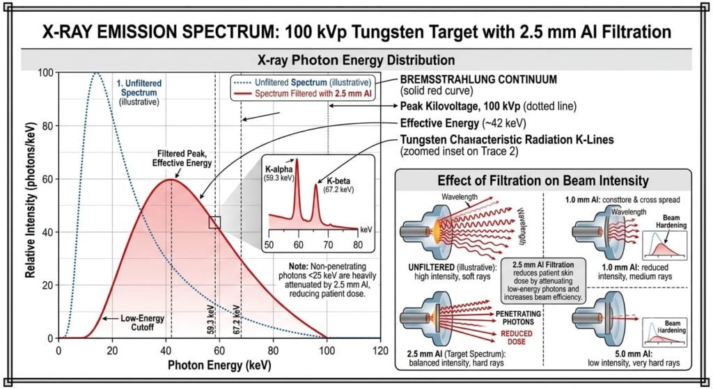
If the accelerating voltage across the X-ray tube between cathode and anode were about 100 kV, the spectrum of radiation that would be used for radiology might be something like that shown in Figure . The various features of this spectrum will now be discussed.
The Continuous Spectrum
When a fast-moving electron strikes the anode, several things may happen. The most common is that the electron will suffer a minor interaction with an orbital electron as depicted at (a) in Figure . This will result in the transfer of a small amount of energy to the target which will appear eventually as heat. At diagnostic energies, at least 99% of the electron energy is converted into heat and the dissipation of this heat is a major technical problem.
Occasionally, an electron will come close to the nucleus of a target atom, where it will suffer a much more violent change of direction because the charge and mass of the nucleus are much greater than those of an electron (example b). The electron does not penetrate the nucleus because the energy barrier presented by these positive charges in the nucleus is far in excess of the electron energy. This results in the electron being deviated around it. The interaction results in a change in kinetic energy of the electron and the emission of electromagnetic radiation, that is in the X-ray range of the spectrum. The amount of energy lost by the electron in such an interaction is very variable and hence the energy given to the X-ray photon can take a wide range of values. Note that X-ray emission may occur after two or three earlier slight deviations (example c). Therefore not all emissions occur from the surface of the anode. This factor is important when the spatial distribution of X-ray emission is considered.
Shape of the Continuous Spectrum
A detailed treatment of the continuous spectrum is beyond the scope of this book, but the following approach is helpful since it involves some other important features of the X-ray production process. First, imagine a very thin anode, and consider the production of X-rays, not the X-rays that finally emerge. It may be shown by theoretical arguments that the intensity of X-rays produced will be constant up to a maximum X-ray energy determined by the energy of the electrons (see Figure a).
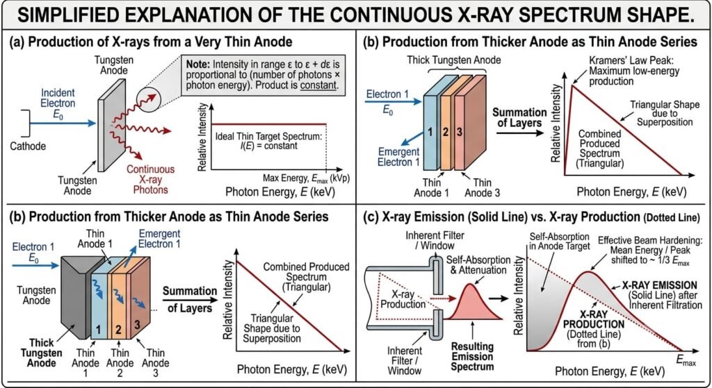
A thick anode may now be thought of as composed of a large number of thin layers. Each will produce a similar distribution to that shown in Figure a, but the maximum photon energy will gradually be reduced because the incident electrons lose energy as they penetrate the anode material. Thus, the composite picture for X-ray production might be as shown in Figure b.
However, before the X-rays emerge, the intensity distribution will be modified in two ways. First, X-rays produced deep in the anode will be attenuated in reaching the surface of the anode and second, all the X-rays will be attenuated in penetrating the window of the X-ray tube. Both processes reduce the intensity of the low energy radiation more than that of the higher energies so the resultant is the solid curve in Figure c.
Effective Energy
Two properties of the spectrum that are sometimes mentioned are the photon energy at which the intensity is maximum (εImax) and the mean energy (εmean). Since the spectrum is not symmetrical, they are not the same and neither has much practical significance.
A more useful quantity is the effective energy (εeff). This is defined as the energy of a narrow beam of monochromatic radiation that would have the same penetrating power (measured in terms of half value layer (HVL) or linear attenuation coefficient) as the mixed energy spectrum. For a well-filtered beam εeff will be close to, but not identical with εImax and approximately one-third εmax.
Line or Characteristic Spectra
Superimposed on the continuous spectrum there may be a set of line spectra which result from an incoming electron interacting with a bound orbital electron in the target. If the incoming electron has sufficient energy to overcome the binding energy, it can remove the bound electron creating a vacancy in the shell. The probability of this happening is greatest for the innermost shells. This vacancy is then filled by an electron from a higher energy level falling into it and the excess energy is emitted as an X-ray. Thus, if, for example, the vacancy is created in the K shell, it may be filled by an electron falling from either the L shell, the M shell or the outer shells. Even a free electron may fill the vacancy but the most likely transition is from the L shell. The process is summarised in Figure .
As discussed in Section 1.1, orbital electrons must occupy well-defined energy levels
and these energy levels are different for different elements. Thus the X-ray photon emitted when an electron moves from one energy level to another has an energy equal to the difference between the two energy levels in that atom and hence is characteristic of that element.
Reference to Figure 1.2b shows that the K series of lines for tungsten (Z = 74) will range from 58.5 keV (for a transition from the L shell to the K shell) to 69.5 keV (if a free electron fills the K shell vacancy). Transitions to the L shell are of little practical importance in diagnostic radiology since the maximum energy change for tungsten is 11 keV and photons of this energy are normally absorbed before they leave the tube.
Lower atomic number elements produce characteristic X-rays at lower energies. The K shell radiations from molybdenum (Z = 42) at circa 19 keV are important in mammography. Note that characteristic radiation cannot be produced unless the operating kV of the X-ray tube is high enough to give the accelerating electrons sufficient energy to remove the relevant bound electrons from the anode target atoms.

Factors Affecting the X-ray Spectrum
If the spectrum changes in such a manner that its shape remains unaltered, that is, the intensity or number of photons at every photon energy changes by the same factor, there has been a change in radiation quantity. If on the other hand, the intensities change such that the shape of the spectrum also changes, there has been a change in radiation quality (the penetrating power of the X-ray beam). A number of factors that affect the X-ray spectrum may be considered.
1 Tube Current, IT
This determines the number of electrons striking the anode. Thus the emitted X-ray energy or exposure E is proportional to tube current, but only the quantity of X-rays is affected (E ∝ IT).
2 Time of Exposure
This again determines the number of electrons striking the anode so exposure is proportional to time but only the quantity of X-rays is affected (E ∝ t).
3 Applied Voltage If other tube operating conditions are kept constant, the output increases approximately as the square of tube kilovoltage (E ∝ kV2). Two factors contribute to this increase. First the electrons have more energy to lose when they hit the target. Second, as shown in Table 2.1, the efficiency of conversion of electrons into X-rays rather than into heat also increases with tube kilovoltage by a small amount over diagnostic energy changes (the change associated with a large increase in kV is shown to emphasise the effect). Thus both the flux of X-ray photons and their mean energy increases. Increasing the tube kilovoltage also alters the radiation quality since the high energy cutoff has now increased. The position of any characteristic lines will not change.
4 Waveform of Applied Voltage
So far it has been assumed that the X-ray tube is operating from DC with a fixed voltage. In fact the voltage is generated by rotating a coil of wire in a magnetic field and changes in magnitude as the position of the coil changes relative to the direction of the field. Thus the magnitude of the voltage changes sinusoidally with time (Figure a) and produces AC. Since in one end of the X-ray tube must act as a ‘cathode’ and the other end as ‘anode’, no current flows when an alternating potential is applied during the half cycle when the cathode is positive with respect to the anode. Half wave rectification (Figure b) may be achieved by inserting a rectifier in the anode circuit but since X-rays are only emitted for half the cycle, output is poor. Improved output can be achieved by full wave rectification obtained by using a simple bridge circuit. However, the tube is still not emitting X-rays all the time (Figure c). Furthermore, the majority of X-rays are emitted at a kilovoltage below the peak value (kVp). A more constant voltage will improve the quality of the radiation and this can be achieved by using a three phase supply. This uses three rotating coils arranged such that, at any instant they are in different positions relative to the magnetic field. The X-ray tube is now driven by three separate voltage supplies, each of which has been fully rectified. The three supplies are 60° out of phase and switching circuits ensure that each supply only drives the X-ray tube when the voltage is near to peak value. The resultant voltage profile (Figure d) shows only about 15% variation. If the cathode supply is also three phase and is arranged to be 30° out of phase with the anode supply, a 12 peak generator is possible and fluctuations can be reduced to about 6%. With high frequency generators used routinely nowadays, an almost constant voltage output can be achieved after rectification and smoothing.
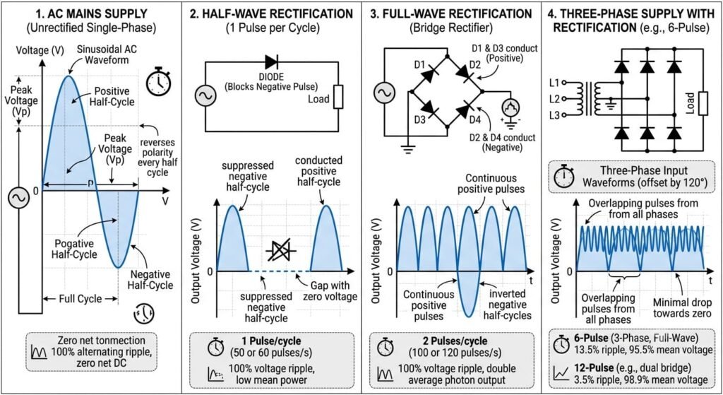
Variation in the voltage supply is known as the voltage ripple and is defined as Vmax – Vmin/ Vmax. Variations in V will affect the instantaneous output. For general radiography a ripple of 5% may be acceptable, but when highly uniform X-ray output is essential, for example, in computed tomography (CT), ripple must be reduced to less than 1%. This subject is considered in more detail in . In future, in accordance with standard practice, operating voltages will be expressed in kVp to emphasise that the peak voltage with respect to time is being given.
5 Filtration
This also has a marked effect on both the quantity and quality of the X-ray beam, not only reducing the overall output but also reducing the proportion of low energy photons. Special filters (K-edge filters) can be used to create a window of transmitted X-ray energies and thus reduce the number of both high and low energy photons. The effect of beam filtratio is considered in detail in Section 3.9.
6 Anode Material
Choice of anode material affects the efficiency of bremsstrahlung production (the continuous spectrum) with unfiltered output increasing approximately proportional to the atomic number of the target. The position of the characteristic lines also moves to higher energies as atomic number increases.
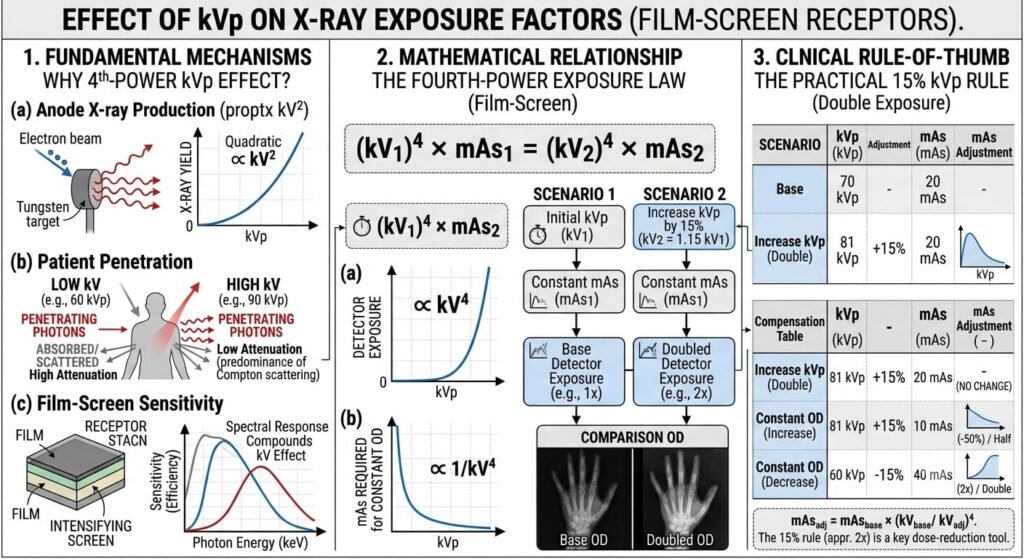
Effect of kV on Exposure Factors-
Note that the effect of increasing kV on the amount of radiation (mAs) required for an exposure is generally greater than that implied by E ∝ kV2. At higher kV the radiation penetrates the patient more easily and detector sensitivity varies with kV. For a film-screen receptor a very approximate relationship between kV1 and kV2
(kV1)4× mAs1 = (kV2)4 × mAs2