Spatial Distribution of X-rays-
When 40 keV electrons strike a thin metal target, the directions in which X-rays are emitted are as shown in (Figure 1 a). Most X-rays are emitted at angles between 45o and 90o to the direction of electron travel. The more energetic X-rays travel in a more forward direction (smaller value of θ). It follows that if the mean X-ray energy is increased by increasing the energy of the electrons, the lobes are tilted in the direction of the electron flow.
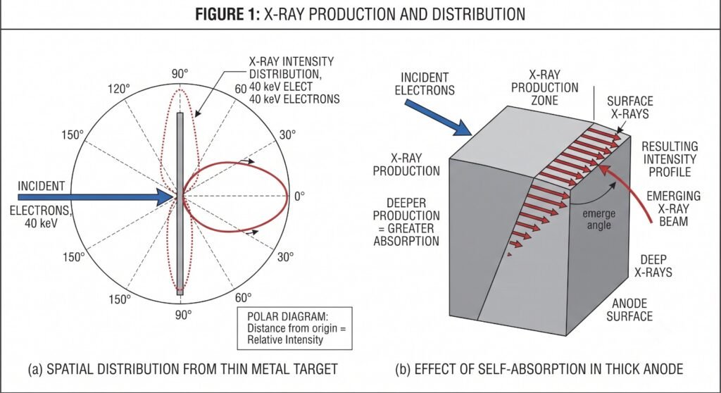
When electrons strike a thick metal target, the situation is more complicated because X-ray production may occur from the surface or it may occur at depth in the target. Also, the spatial distribution of X-rays will now depend on the angle presented by the anode to the incoming electron beam. Consider the anode shown in (Figure 1 b) with an anode angle of 30o. (Note carefully which angle is defined as the anode angle.)
(Anode angle—the angle between the anode surface and the electron beam is 90-α or 600 in this instance.)
X-rays produced in the direction B are much more heavily attenuated than those produced in the direction A because they travel further through anode material. This is clearly a disadvantage since a primary objective of good X-ray tube design is to ensure that the field of view is uniformly exposed to radiation. Only if this is achieved can variations in receptor response, for example, film blackening, be attributed to variations in scatter and absorption within the patient. Variation in intensity across the field is minimised by carefully selecting the angle at which the anode surface is inclined to the vertical (Figure 2).
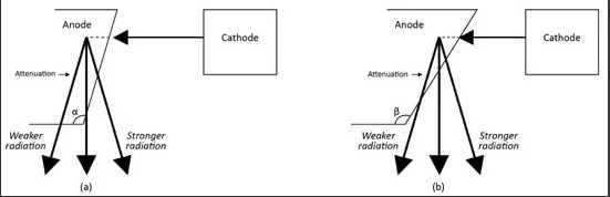
Note the following additional points:
1. The radiation intensity reaching the detector is still not quite uniform, being maximum near the centre of the field of view. This is due to
(a) An inverse square law effect—radiation reaching the edges of the field has to travel further
(b) A small obliquity effect—beams travelling through the patient at a slight angle must traverse a greater thickness of the patient and are thus more attenuated
Neither of these factors is normally of great practical importance.
2. The anode angle selected does not remove the asymmetry completely and this is known as the heel effect. The effect of X-ray absorption in the target, which results in a bigger exposure at A than at B, is more important than asymmetry in X-ray production, which would favour a bigger exposure at B.
3. Some compensation for the heel effect can be achieved by tilting the filter. The left hand edge of the beam will pass through a smaller thickness of filter than the right hand edge. This modification is being used in some mammography tubes.
4. No such asymmetry exists in a direction normal to that of the incident electron beam so if careful comparison of the blackening on the two sides of the film is essential the patient should be positioned accordingly although care must be taken balancing a tall patient at right angles to the table.
5. The shape of the exposure profile is critically dependent on the quality of the anode surface. If the latter is pitted owing to overheating by bombarding electrons, much greater differences in exposure may ensue.
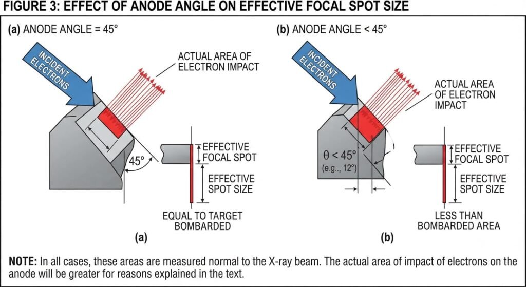
6. An angle of about 13o–16o is frequently chosen for general radiography and this has one further benefit. One linear dimension of the effective spot for the production of X-rays is less than the dimension of the irradiated area by a factor equal to sin α. Sin 13o is about 0.2, so angling the anode in this way allows the focusing requirement on the electron beam to be relaxed whilst ensuring a good focal spot for X-ray production (Figure 3). This is known as the line focus principle. If a very small focal spot (∼0.3 mm) is required, a smaller angle, perhaps only 6o may be used. Note that with a small anode angle, the heel effect greatly restricts the field size. This may not be a problem if the field of view is inherently small but, in general, the only compensation is to increase the focus-receptor distance. For example, if the minimum acceptable variation in optical density across the field of view is 0.2, for a film size of 43 cm × 35 cm the minimum focus-film distance increases from about 110 cm for a 16o angle to 150 cm for a 12o angle. There is a consequent loss of intensity at the film due to the inverse square law. Some X-ray tubes have used anodes with two angles so that the best angle for the focal spot size chosen can be used, but this is rare now.
Even with a well-designed anode, a certain amount of extrafocal radiation arises from regions of the anode out with the focal spot. These X-rays may be the result of poorly collimated electrons but are more usually the consequence of secondary electrons bouncing off the target and then being attracted back to the anode remote from the focal spot. Note that extrafocal radiation is not scattered radiation. Extrafocal X-rays may contribute as much as 10%–15% of the total output exposure of the tube but are of lower average energy. Many of them will fall outside the area defined by the light beam diaphragm and under extreme conditions may cast a shadow of the patient (Figure 4).
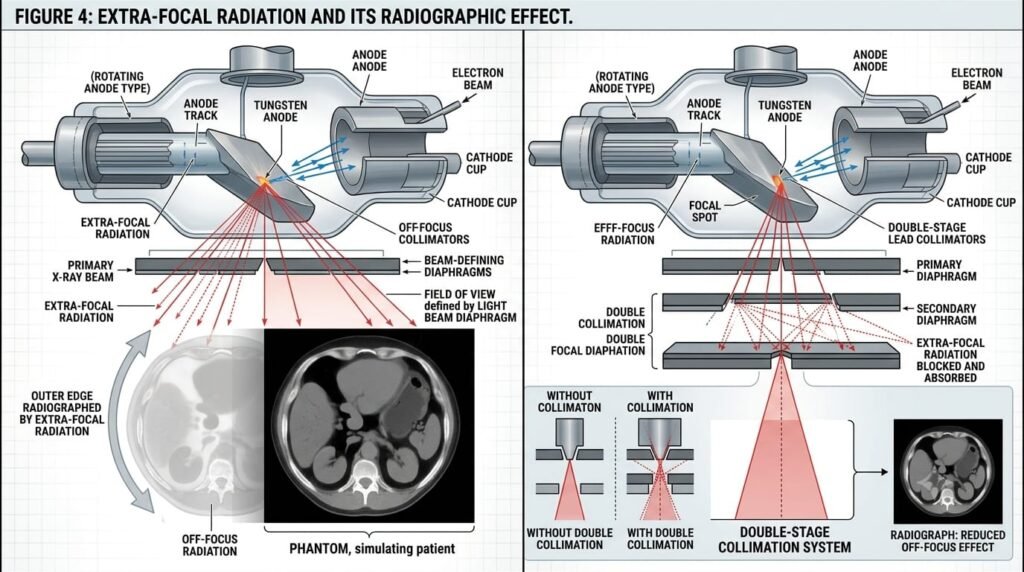
Over the region of interest, the principal effect of extrafocal radiation is that it creates a uniform low level X-ray intensity. This contributes to the reduction in contrast produced by scattered radiation. Since this reduces image quality and hence, indirectly, increases the dose for imaging, it remains an important consideration. An additional effect is an increase in geometric blurring (enlarged effective spot size).
Secondary Collimation
Note that some of the X-ray photons from off-focus sources can be stopped by secondary collimation— a second set of collimators placed below the first set (Figure 5). This double collimation acts somewhat like a parallel hole collimator in a gamma camera.
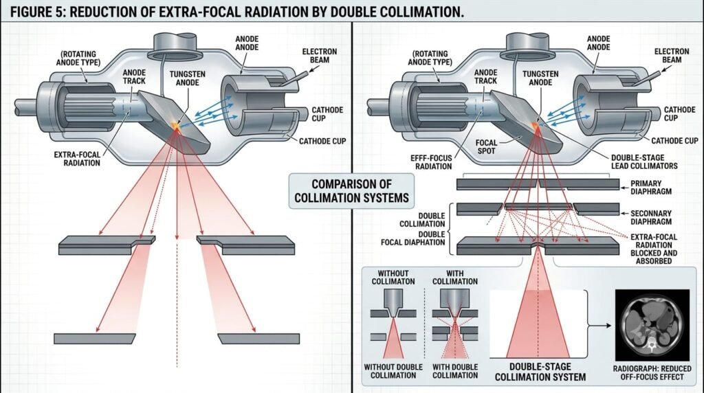
With rotating anode tubes extrafocal radiation is generated on the anode plate—that is, in a strip perpendicular to the tube axis, so the effect is most clearly visible on edges of the radiograph that are parallel to the axis of the X-ray tube. In the metal cased tubes the case is at earth potential and attracts off-focus electrons. The amount of off-focus radiation produced is reduced but not eliminated.
Extrafocal radiation is a potentially serious problem in image intensifier fluoroscopy because if unattenuated radiation reaches the input screen of the image intensifier the very bright fluorescent areas reduce contrast by light scattering and light conduction effects. The effect of extrafocal radiation on receptors in digital radiology probably merits investigation