Components of the X-ray Tube-
The Cathode-
The cathode assembly normally consists of two parts—
(a) an electron source (emitter) and
(b) an auxiliary electrode surrounding it.
The electron emitter is usually a coiled wire filament 0.2–0.3 mm in diameter of reasonably high resistance R. Therefore, for a given filament heating current IF (typically in the region of 5A), effective ohmic heating (IF2R) and minimum heat losses will occur. A metal is chosen for the cathode that will give a copious supply of electrons by thermionic emission at temperatures where there is very little evaporation of metal atoms into the vacuum (e.g. tungsten, melting point of 3370°C). These electrons form the tube current IF. Note that the emission current response time is slow so controlling electron emission is not a practical means of controlling the time of X-ray exposure.
The tube current increases exponentially with increasing filament current and might, typically, rise by four orders of magnitude if the filament temperature increased from 2000 K to 3000 K (but note the adverse effect on tube lifetime). Also if IF and IT are too high it will be difficult to focus the electron beam. Thus the filament is kept well below its melting point.
Between exposures, the filament is kept warm on stand-by because although its resistance may be typically 5 Ω at 2000°K, at room temperature it falls to about 0.1 Ω. Thus a large current would be required to heat the filament rapidly from room temperature to its working temperature. Surrounding the filament is a cloud of negatively charged electrons, commonly called the space charge. The number of electrons in the space charge tends to a self-limiting constant value dependent on the filament temperature.
For reasons related primarily to geometrical unsharpness in the image, a small target for electron bombardment on the anode is essential. However, unless special steps are taken, the random thermally induced velocities and mutual repulsion of the electrons leaving he cathode will cause a broad beam to strike the anode. Therefore the filament is surrounded by an auxiliary electrode, or focussing cup (the Wehnelt electrode), typically made of nickel. This electrode provides an electric field which exercises a focusing action on the electrons by changing the equipotential lines and pressing the electrons together to produce a small focal spot on the anode. Originally, the Wehnelt electrode was maintained at the same potential as the emitter but smaller spots can be obtained by making its potential slightly more negative.
If the Wehnelt electrode is made about 2 kV more negative than the filament, or an additional electrode or ‘grid’ is used to provide this voltage, the electron beam will be stopped completely. This technique, known as grid control, can be used to improve the output profile of the X-rays since pulsed control of the current switches the beam on and off with very little inertia. A more recent alternative method of output control is primary pulsing. This is one of the benefits of recent developments in high frequency generation and permits the direct modulation of tube voltage. Output profiles with steep rise and fall times are important when rapid pulses or very short exposures (a few milliseconds) are required, for example in fluorography, digital subtraction angiography, CT and paediatrics. Most diagnostic X-ray tubes have a choice of focal spot size. A smaller focal spot produces sharper images but places greater demands on heat dissipation in the anode .
Some tubes have a dual filament assembly, each filament having its own focusing cup producing two spots of different sizes. Alternatively, the negative voltage bias on the Wehnelt electrode may be varied to refocus the electron output from a single filament electrostatically. Note that spot size does vary somewhat with tube current and tube kilovoltage since the focusing action cannot be readily adjusted to compensate for variations in the mutual electrostatic repulsion between electrons when either their density or their energy changes. The effect may not be apparent if tube current is increased from 100 mA to 300 mA at 140 kVp but at 80 kVp the focal spot size may increase by a factor of two or more. The effective or apparent size of the focal spot on the anode is smaller than the actual focal spot because of the anode angle. The smaller the anode angle the smaller the apparent focal spot size
The Anode Material-
The material chosen for the anode should satisfy a number of requirements. It should have
1. A high conversion efficiency for electrons into X-rays. High atomic numbers are favoured since the X-ray intensity is proportional to Z. At 100 keV, lead (Z = 82) converts 1% of the energy into X-rays but aluminium (Z = 13) converts only about 0.1%.
2. A high melting point so that the large amount of heat released causes minimal damage to the anode.
3. A high conductivity so that the heat is removed rapidly
4. A low vapour pressure, even at very high temperatures, so that atoms are not boiled off from the anode.
5. Suitable mechanical properties for anode construction.
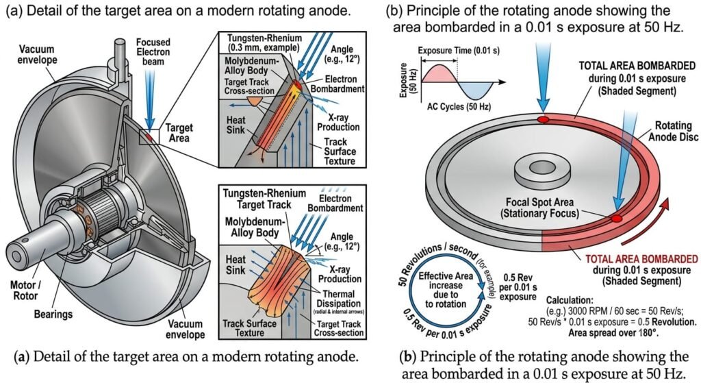
In stationary anodes the target area is pure tungsten (W) (Z = 74, melting point 3370°C) set in a metal of higher conductivity such as copper. Originally, rotating anodes were also made of pure tungsten. However, at the high temperatures generated in the rotating anode (see Section 2.3.3), deep cracks developed at the point of impact of the electrons. The deleterious effects of damaging the target in this way are discussed in Sections 2.3.5 and 2.4. The addition of 5%–10% rhenium (Rh) (Z = 75, melting point 3170°C) greatly reduced the cracking by increasing the ductility of tungsten at high temperatures. The wear resistant rhenium alloy in the focal spot path ensures minimal ageing, thus high and constant exposure values for a long life. However, pure W/Rh anodes would be extremely expensive so molybdenum is now chosen as the base metal. Molybdenum (Z = 42, melting point 2620°C) stores twice as much heat, weight for weight, as tungsten, but the anode volume is now greater because molybdenum has a smaller density than tungsten. As shown in Figure 2.7a only a thin layer of W/Rh is used to prevent distortion that might arise from the differences in thermal expansion of the different metals.
Anode Design-
The two principal requirements of anode design are first to make adequate arrangements for dissipation of the large quantity of heat generated and second to ensure a good spatial distribution of X-rays. Design features related primarily to heat dissipation are discussed below, the spatial distribution of X-rays is considered later.
Stationary Anode-
Previous blog shows the design of a relatively simple X-ray tube with a stationary anode. When low outputs suffice, for example in dental and small mobile units, stationary anodes may still be used. Tungsten in the form of a small disc about 1 mm thick and 1 cm in diameter is embedded in a large block of copper which protrudes through the tube envelope into the surrounding oil. Heat is transferred from the tungsten to copper by conduction and thence to the oil by convection. The cooling fins assist the convection process. The oil transfers this heat to the X-ray tube shield by conduction and it is eventually removed by air in the X-ray room by convection. A stationary anode tube is simple, robust, very reliable and has a long lifetime, but its low power makes it unsuitable for many radiographic applications.
Rotating Anode-
For reasons related almost entirely to heating effects in the anode, the majority of diagnostic X-ray tubes currently use rotating anodes. Such a tube is shown schematically in (Figure ) and the discussion will focus primarily on this design. The principle of the rotating anode is very simple (Figure b) but its design has two important features to assist heat dissipation. First, as shown in (Figure a), the anode surface is steeply angled to the electron beam. If the required focal spot size on the target is, say 2 mm × 2 mm, for an anode angled to the beam at about 16° the dimensions of the area actually bombarded by electrons are about 6 mm × 2 mm . Second the area over which heat is dissipated can be increased considerably by arranging for the tungsten target to be an annulus of material which rotates rapidly (see Figure b).
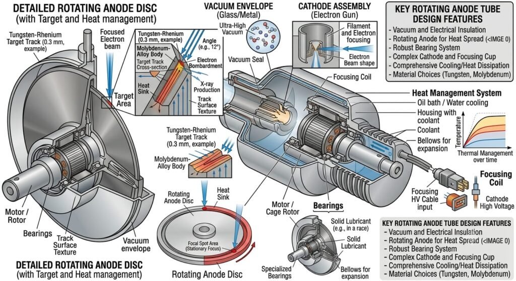
For the 80 mm diameter anode suitable for general radiographic work shown in (Figure b). When high loading is required, that is high heating rates and high heat storage capacity, anodes up to 200 mm in diameter may now be used. In addition to anode size, surface area, disc mass and rate of rotation all affect the loading. If a graphite block is brazed onto the back of an anode, its low mass and high melting point increase the heat storage capacity, and the heat radiating efficiency is increased because of the bigger anode surface and the better emission coefficient of black graphite.
Rotation rates range from 3000–3600 rpm with 50–60 Hz mains supply, up to 9–10,000 rpm with a 3-phase supply, ensuring that the anode rotates several times during even the shortest exposure, thus maximising the area over which the heat is distributed. However, this does create some problems with respect to the type of mounting and cooling mechanism. Adequate electrical contact is maintained via bearings on which the anode rotates, but the area of contact is quite insufficient for adequate heat conduction. Either ball bearings or sleeve bearings may be used.
Bearing Systems-
Such systems must overcome very challenging requirements:
• They form a connection between a very hot anode plate and a cold environment.
• They must operate in a vacuum.
• They must withstand high turning speeds and weight loads.
Lubrication of ball bearings cannot be by oil or grease because of the vacuum required in the X-ray tube. However, the lubricants must be soft, deformable materials that are stable at high temperatures and have low vapour pressure under vacuum. Dry metallic lubricants such as silver paste are used.
A recent development is the introduction of liquid, sliding bearings which utilise the aquaplaning effect of liquid metals. A good analogy is a locked car wheel on a wet road surface. Water accumulates between the tyre and road and forms a bow wave. As pressure builds a wedge is created between them and eventually a film of water is forced in, separating the tyre and road along the whole contact area. For sliding bearings a liquid metal (e.g. an eutectic of gallium, indium and tin which melts at –10oC) is used in a 20 µm gap. An important advantage of the new design
is the extra anode cooling (1–2 kW) by fast heat flux from the anode through the liquid metal into the cooling system.
Since the anode is an evacuated tube, there are no heat losses by convection. The initial mode of heat transfer from the anode to the cooling oil must therefore be primarily by radiation at a rate proportional to (anode temperature)4 − (oil temperature)4. With a rotating anode, heat loss by conduction along the anode support is actually minimised since it
Rotating Envelope-
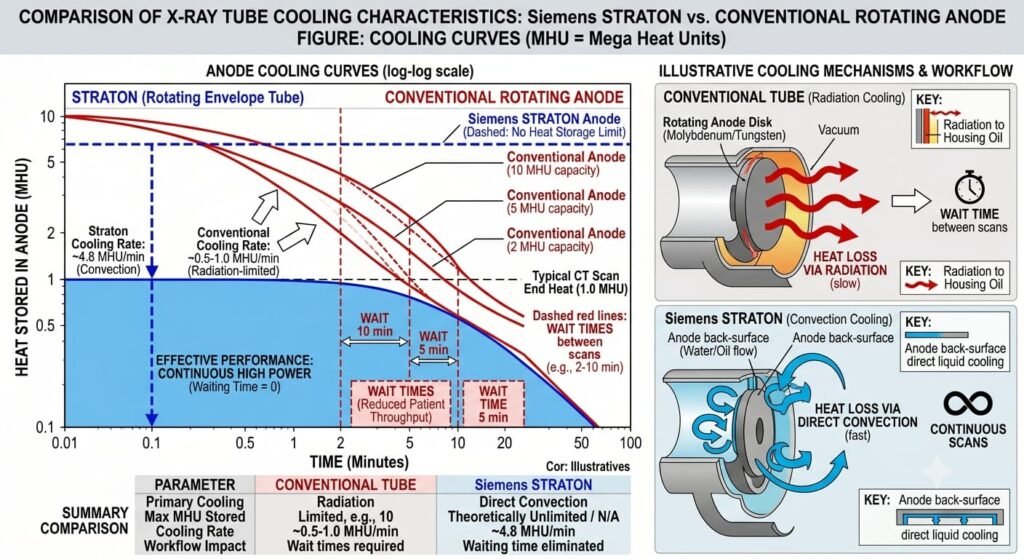
In a recent development which permits even more efficient heat dissipation, the anode is an integral part of the tube envelope and both of them rotate. The whole tube rotates around a symmetry axis with a single electron emitter at the centre of rotation. The electron beam is continuously deflected by magnetic fields to a fixed spot in space on the anode plate. The anode still rotates so heat is distributed around the focal ring and performance for brief high-power X-ray generation is similar to that of a cold rotating conventional anode. However, since the rear of the anode is now directly exposed to cooling agent (c.f. the stationary anode) it cools quickly and no extra heat storage is required. Enhanced cooling compared to conventional tubes is shown in( Figure). Note that this extra heat loss is by conduction not radiation.