

Switching and Timing Mechanisms-
Most Switching and Timing Mechanisms takes place in the primary circuit of the high voltage transformer where, although the currents are high, the voltage is low. Switching in the high voltage secondary circuit is only undertaken if very short exposures are required or exposures must be taken in quick succession.
Primary Switches
These are now almost all based on a thyrister which is a solid state controlled rectifier turned on and off by a logic pulse. A small positive logic pulse allows the thyrister to avalanche and a large current to flow which operates a relay closing the primary circuit. The switching is very rapid and is suitable for most radiographic exposures. The circuit used to drive the device is, however, quite complicated and beyond the scope of this book.
Switching the high voltage side of the transformer can be undertaken in two ways. The large electrical power that has to be accommodated (up to 100 kW) precludes the use of solid state devices and triode valves have to be used. Alternatively the exposure can be regulated with the Wehnelt electrode (grid control). This grid is used to switch the tube on and off very rapidly by changing its voltage from negative to just positive relative to the cathode. When negative, even though the full kVp is applied across the tube, electrons cannot move from the cathode to the anode.
Timing Mechanisms
Accurate timing of an exposure is more complex than simply recording the ‘on’ time and ‘off’ time. As shown in Figure 2.15, there is a lag time before the kV builds to its full value, a brief delay before the kV responds to the ‘exposure off’ command and then a further lag as the kV decays.
The Electronic Timer
For simple adult radiography the ‘on’ time is long compared to the uncertainties and can be measured adequately with an electronic timer. If a capacitor C is charged to a fixed potential Vo, either positive or negative, and then placed in series with a resistor R, the rate of discharge of the capacitor depends on the values of C and R. A family of curves for fixed C and variable R is shown in Figure 2.16. Note that a large resistance reduces the rate of flow of charge so the rate of fall of V is slower.
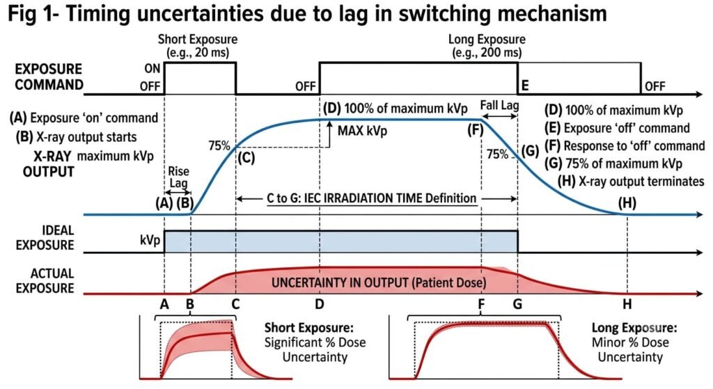
Timing uncertainties due to lag in switching mechanism. (A) Exposure ‘on’ command; (B) X ray output starts; (C) 75% maximum kVp; (D) 100% of maximum kVp; (E) Exposure ‘off’ command; (F) Response to ‘off’ command; (G) 75% of maximum kVp; (H) X-ray output terminates. C to G is the International Electrotechnical Commission (IEC) definition of irradiation time. There is a corresponding uncertainty in output (patient dose), shown shaded. The shorter the exposure, the greater the percentage uncertainty.
These curves may be used as the basis for a timer if a switching device is arranged to operate when the potential across C reaches say Vs.
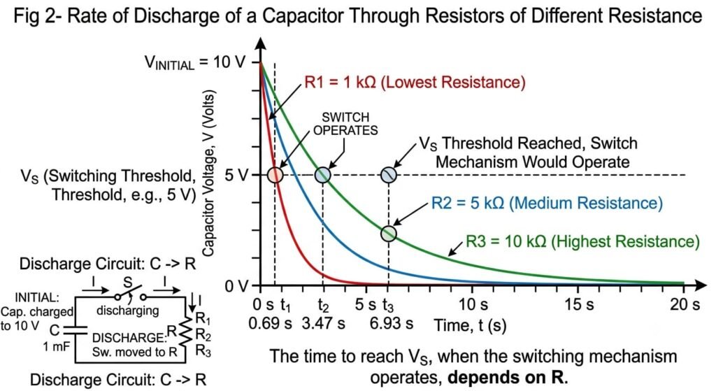
Curves showing the rate of discharge of a capacitor through resistors of different resistance. The time taken to reach VS when the switching mechanism would operate, depends on the value of R.
Frequency or Pulse Counting Timers
When very short exposures or a series of short exposures are required (e.g. in paediatrics and digital subtraction angiography, respectively) errors in the exposure profile may be important and the electronic timer responds too slowly. New high frequency inverter systems based on transistor technology (see Section 2.3.4) have greatly reduced exposure uncertainties associated with switching. Furthermore with a medium frequency generator, pulses are being generated at a rate of 5–15 kHz. Thus an alternative way to think of mAs is charge/pulse × number of pulses. Hence for a preset mAs the exposure can be controlled simply by counting the required number of pulses. This pulse counting timer would be accurate to ±1 pulse, or at a frequency f = 5 kHz 1/10,000 s (there are two pulses/cycle). Since the error in charge (ΔQ) would be the current flowing I multiplied by the time of one pulse ΔQ = I/2f.
For a current of 1000 mA
The Photo Timer-
The weakness of any timer that predetermines the exposure is that a change in any factor which affects the amount of radiation actually reaching the receptor, notably patient attenuation, will alter the response. For a digital detector it may be possible to adjust for this by altering the window level (see Section 6.3.3) but for film the blackening will change.
Thus the skill of the radiographer in estimating the thickness of the patient and choosing the correct exposure is of great importance. In the photo timer the exposure is linked more directly to the amount of radiation reaching the receptor. This is known as automatic exposure control or AEC.
One design, used especially when film is the receptor, places small ionisation chamber monitors in the cassette tray system between the patient and the film-screen combination. The amount of radiation required to produce a given degree of film blackening with a given film-screen combination under standard development conditions is known, so when the ion chamber indicates that this amount of radiation has been received, the exposure is terminated. This type of exposure control does not need to be ‘set’ before each exposure, but some freedom of adjustment is provided to allow for minor variations in film blackening if required. Adjustment will also be required if screens of different sensitivity are used.
As an alternative to ion chambers, photomultiplier tubes (see Section 4.8) may be used after the X-rays have been converted to light by a phosphor. Some have the disadvantage, however, of being X-ray opaque so they must be placed behind the cassette, where the X-ray intensity is low, and special radiolucent cassettes must be used. Others use phosphor- coated lucite, which can be placed in front of the cassette as it does not attenuate the X-ray beam. The light produced is internally reflected to the side where the photomultiplier can view it. The energy response of the phosphor probably differs from that of the receptor and some form of compensation must be built into the circuitry by using software control.
A weakness with some types of phototimer is that the ion chamber or photomultiplier tube only monitors the radiation reaching a small part of the receptor and this may not be representative of the radiation reaching the rest of the receptor. This problem can be partially overcome by using several small ion chambers, usually three, and controlling the exposure with the one, that is, closest to the region of greatest interest on the resulting image.
There must also be a backup exposure timer so that should the AEC fail, the patient exposure, although longer than necessary, will be terminated without intervention by the operator. It should be noted that this backup time should not be set at the thermal limit of the tube as this could result in a large radiation dose to the patient.
