

Electric Supply In X ray Tube-
Electrical Circuits-
Brief details will be given of the essential electrical components of an X-ray generator.
The Transformer-
This provides a method of converting high ACs at low potential difference to low ACs at high potential difference. It consists of two coils of wire which are electrically insulated from one another but are wound on the same soft iron former (Figure 1 ). If no energy is lost in the transformer-
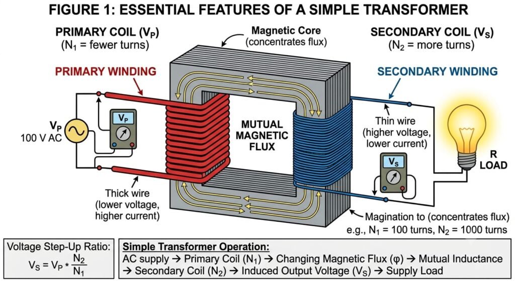
Essential features of a simple transformer.
Vout/Vin=N2/N1
where n1 and n2 are the number of turns on the primary and secondary coils, respectively.
Note
1. By making a connection at different points, different output voltages may be obtained. For example, the alternating potential difference across AB is given by VAB = Vout/3
2. Since, in the ideal case, all power is transferred from the input circuit to the output circuit VinIin =VoutIout
3. Power loss occurs in all transformers, and the amount depends on working conditions, especially Iin. Hence Vout and Iout also vary and auxiliary electrical circuits are required to stabilise outputs from an X-ray set.
4. The efficiency of a transformer increases as the frequency of operation rises and consequently its size decreases.
(Figure (see later) ) also shows, on the extreme left, an autotransformer. An autotransformer comprises one winding only and works on the principle of self-induction. Since the primary and secondary circuits are in contact, it cannot transform high voltages or step up from low to high voltages. However, it does give a variable secondary output on the low voltage side of the transformer and hence controls kV directly.
Generating Different Voltage Wave Forms-
As explained before the alternating potential must be rectified before it is applied to an X-ray set. The X-ray tube can act as its own rectifier (self-rectification) since it will only pass current when the anode is positive and the cathode is negative. However, this is a very inefficient method of X-ray production because if the anode gets hot, it will start to release electrons by thermionic emission. These electrons will be accelerated towards the cathode filament during the half cycle when the cathode is positive and will damage the tube. Thus the voltage supply is rectified independently.
If a gas-filled diode valve or a solid state p-n junction diode rectifier is placed in the anode circuit, half wave rectification (discussed in previous article ) is obtained. Historically, a gas-filled diode, a simplified X-ray tube, comprising a heated cathode filament and an anode in an evacuated enclosure, was used. Electrons may only flow from cathode to anode but the diode differs from the X-ray set in that it is designed so that only a small proportion of the electrons boiled off the cathode travel to the anode. In terms of (Figure 2), which shows the effect of tube kilovoltage on tube current, the diode operates on the rapidly rising portion of the curve, whereas the X-ray tube operates on the near-saturation portion.
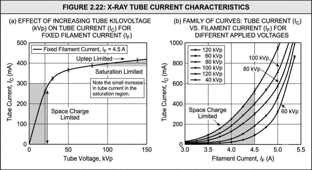
(a) The effect of increasing tube kilovoltage on the tube current for a fixed filament current. (b) A family of curves relating tube current to filament current for different applied voltages.
The design and mode of operation of a p-n junction diode will be considered in next article when its use as a radiation detector is discussed. It has many advantages over the gas-filled diode as a rectifier, including its small size, long working lifetime, and robustness. It is also easy to manufacture in bulk, is inexpensive, requires no filament heating circuit, has a low heat dissipation and a fast response time. For rectification, silicon rectifiers have a number of advantages over selenium, including a negligible forward voltage drop and a very high reverse resistance resulting in negligible reverse current flow. They can also withstand high reverse bias voltages so only a few hundred silicon rectifiers are required rather than a few thousand if made of selenium, and they can work up to 200°C if required.
The essential features of a full wave rectified supply are shown in ( Figure 3).
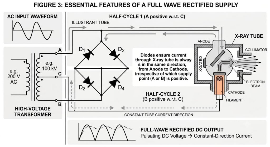
Essential features of a full wave rectified supply (Solid) and (dotted) arrows show that irrespective of whether A or B is at a positive potential, the current always flows through the X-ray tube in the same direction.
Medium and High Frequency Generators-
In these generators a frequency converter—a combination of a rectifier and inverting rectifier sometimes called an ‘inverter’ or ‘thyrister’—is used to convert an AC of one frequency into an AC at a much higher frequency. The first generation of thyrister-based generators typically operated at 5–15 kHz and have become known as medium frequency generators. High frequency generators, with switching frequencies above the audible range, mostly in the range 50–100 kHz, are now the norm. Very high frequency generators up to 500 kHz are being developed. Figure 2.12 summarises the stages in the process.
1. Full wave rectification of the line AC voltage u1 at frequency f1.
2. This provides a DC voltage u0 (after smoothing).
3. Rapid chopping of this DC voltage by the inverter to provide an alternating voltage u2 comparable to u1 at a much higher frequency f2.
4. A high frequency transformer now transforms this to a higher voltage u3 and, after again being rectified and smoothed this voltage is fed to the X-ray tube.
Advantages of the medium and high frequency generators are as follows:
1. High output—The output is very high and comparable with a three phase, 12-peak generator. At 100 kV (virtually DC), 0.1 A gives 10 kW so for a 0.1 s exposure there are 1000 J of energy to dissipate.
2. Reduced voltage ripple—At this high frequency, because pulses are very short the kV never falls very far below its peak value. Thus the average energy of the X-ray photons is higher than for a three phase supply and the output is very constant.
3. Compact size—The transformer equation u/fnA = constant where n is the number of turns on the transformer and A its cross-sectional area, shows that if f is increased by a factor of 100, say from 50 Hz to 5 kHz, nA may be reduced by a similar amount. Since the efficiency has been improved the transformer is much smaller, perhaps one-tenth the size of a three phase 12 peak generator.
4. Rapid response—The high voltage is switched on and off, and its level may be regulated even during exposure, under feed-back control of the inverter. The rise time of the tube voltage can be less than 200 μs.
5. Long-term stability—The tube current is more stable at the higher frequency f2 and is independent of the voltage.
6. Timer precision—The precision of the exposure timer can be improved.
7. Voltage range—The generator may be used across the full kV range from mammography to CT.
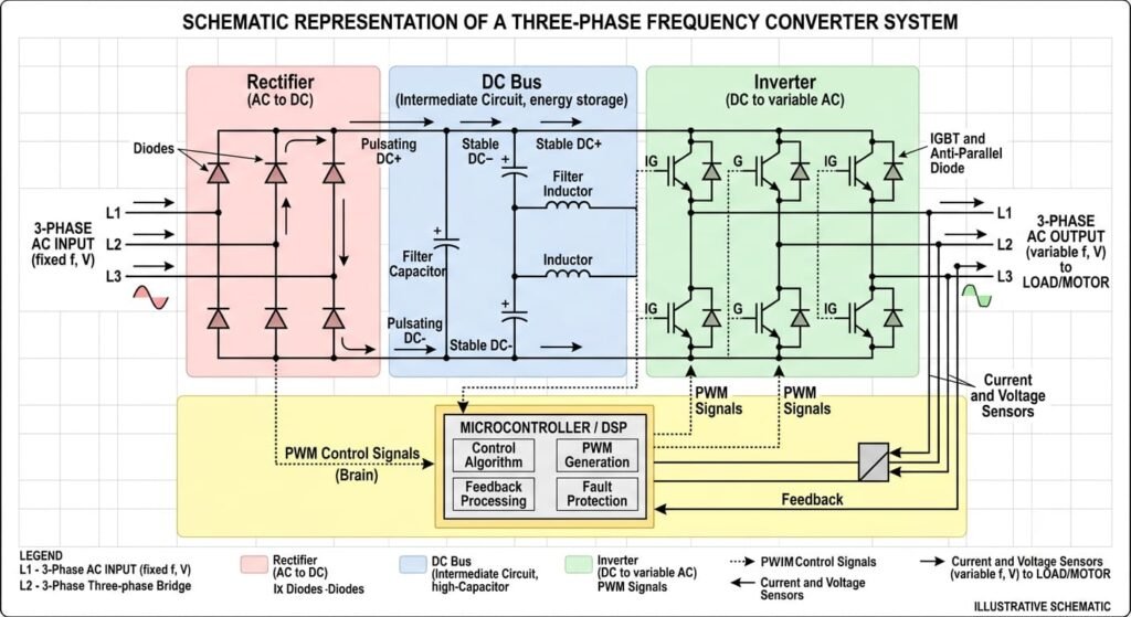
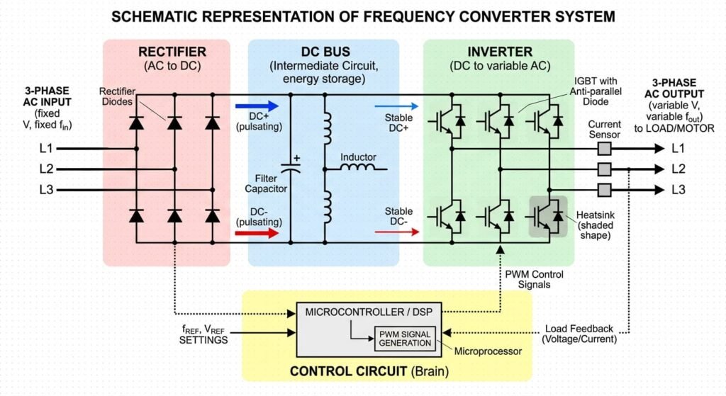
Schematic representation of frequency converter.
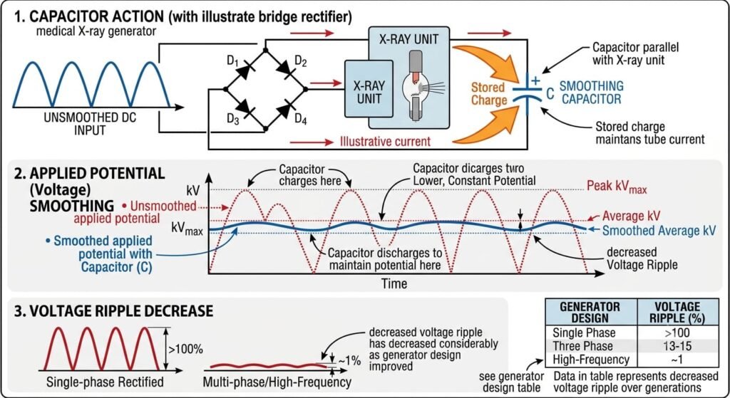
Action of Smoothing Capacitors-
A capacitor in parallel with the X-ray unit will help to smooth out any variations in applied potential (Figure 5.). Consider, for example, the full wave rectified supply . When electrons are flowing from the bridge circuit, some of them flow onto the capacitor plates and are stored there. When the potential across the bridge circuit falls to zero, electrons flow from the capacitor to maintain the current through the X-ray tube. Voltage ripple has decreased considerably as generator design has improved—see Table
Tube Kilovoltage and Tube Current Meters-
These are essential components of the circuit and are shown in relation to other components in Figure 6. Note that the voltmeter is placed in the primary circuit so that a reading may be obtained before the exposure key is closed. There are two ammeters.
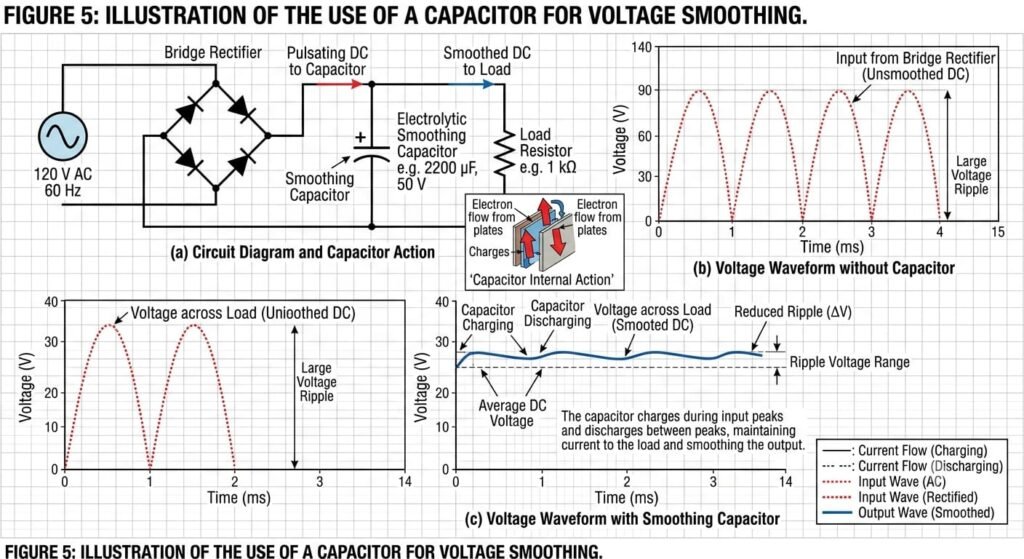
Illustration of the use of a capacitor for voltage smoothing. For explanation see text.
AF measures the filament supply current (IF) which may be adjusted to give the required thermionic emission before exposure starts. The actual tube current flowing during exposure (Ic) is measured by ammeter Ac.
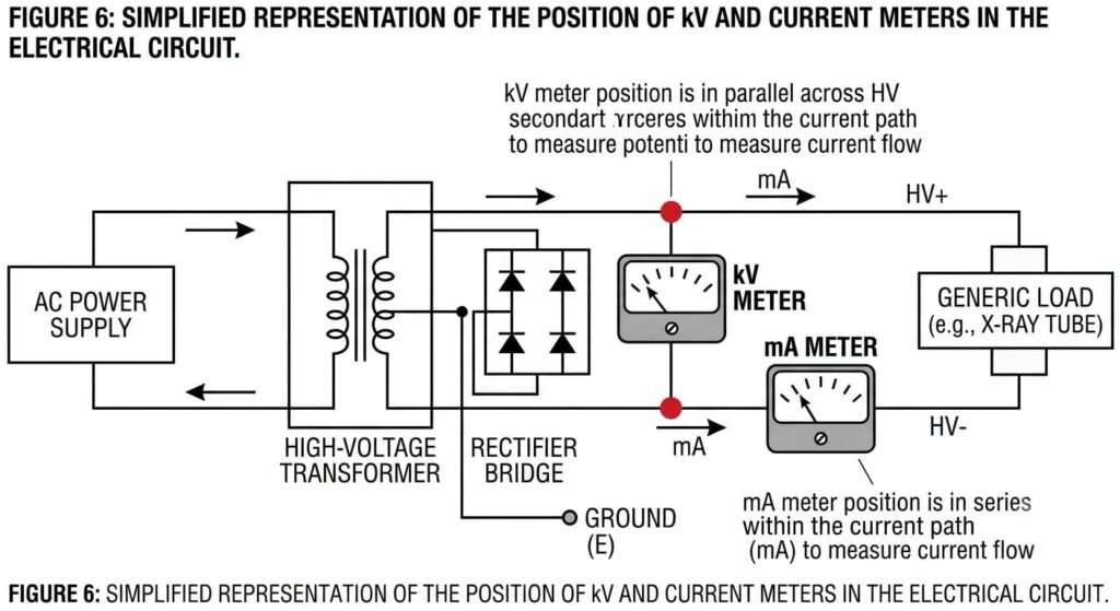
Simplified representation of the position of kV and current meters in the electrical circuit.
