
Submentovertex (SMV) View Radiography: Skull Base & Zygomatic Positioning

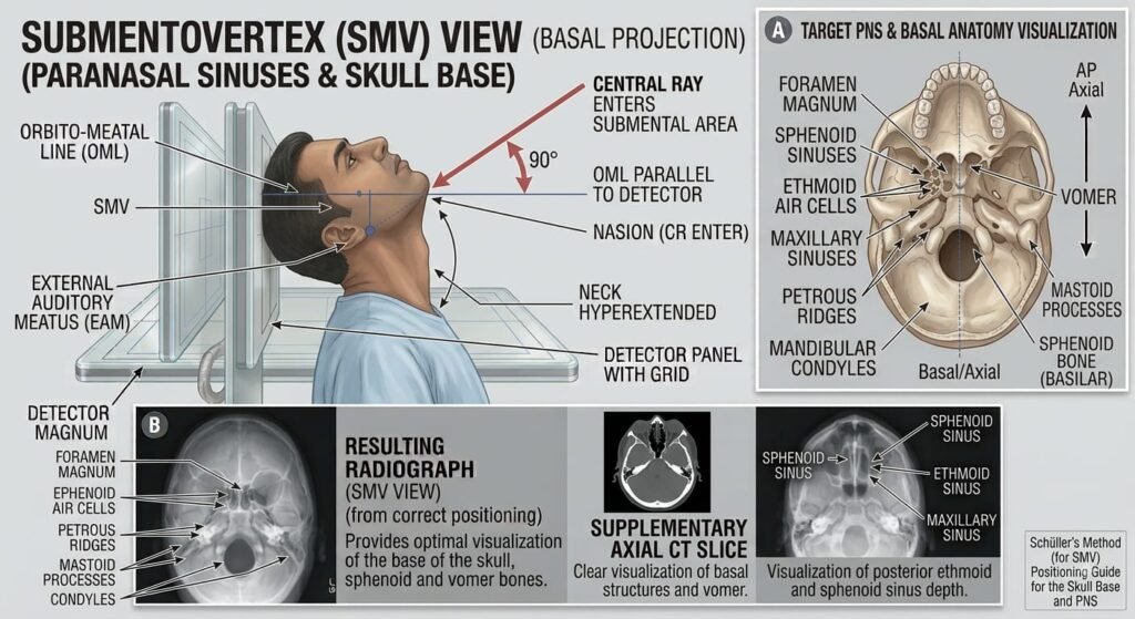
The Submentovertex (SMV) View (also known as the Schüller Method or Full Base View) is an axial projection of the cranium. By hyper-extending the neck so the Infraorbitomeatal Line (IOML) is parallel to the image receptor, the central ray traverses vertically from beneath the chin (submentum) through the cranial vertex, isolating the base of the skull (basilar view), foramina of the middle cranial fossa, sphenoid/ethmoid sinuses, and bilateral zygomatic arches.
1. Clinical Indications & Contraindications
Detailed Indications:
- Basilar Skull Fractures: Detection of fractures traversing the floor of the anterior, middle, or posterior cranial fossae, petrous ridges, and sphenoid bone.
- Cranial Base Foramina Assessment: Direct visualization of the size, symmetry, and cortical margin integrity of the:
- Foramen Ovale (transmits mandibular nerve V3, accessory meningeal artery).
- Foramen Spinosum (transmits middle meningeal artery, recurrent meningeal nerve).
- Foramen Lacerum and Carotid Canals.
- Erosion or enlargement due to acoustic neuromas, nasopharyngeal carcinomas, or glomus jugulare tumors.
- Bilateral Zygomatic Arch Fractures (“Jug-Handle” View): Assessment of depressed or displaced fractures of the slender zygomatic arches without superimposition of the facial bones (using reduced exposure factors).
- Paranasal Sinus Pathology: Direct axial evaluation of the sphenoid sinuses, posterior ethmoid cells, and lateral walls of the maxillary antra.
- Mandibular Condyle & Coronoid Process Integrity: Evaluation of axial alignment, medial/lateral displacement, and symmetry of the mandibular condyles relative to the glenoid fossae.
- Mastoid & Petrous Apex Pathology: Evaluation of petrous apices, mastoid air cell symmetry, cholesteatomas, and chronic petrositis (Gradenigo’s syndrome).
Contraindications & Limitations:
- Unstable / Suspected Cervical Spine Trauma (Absolute Contraindication): Never hyperextend the patient’s neck if there is any history of acute cervical spine injury or un-cleared C-spine imaging. The extreme extension can cause catastrophic spinal cord impingement or transection.
- Severe Cervical Spondylosis / Elderly Kyphosis (Relative): Patients with severe degenerative cervical arthritis, limited neck mobility, or dizziness/vertebrobasilar insufficiency cannot tolerate full extension. Tube angulation must be utilized to compensate.
- High Radiation Dose to Thyroid: Direct beam entry through the submental and anterior neck region delivers direct exposure to the thyroid gland.
2. Technical Factors
| Parameter | Skull Base / Foramina Protocol | Zygomatic Arch Protocol (“Jug-Handle”) | Radiographic Rationale |
|---|---|---|---|
| Patient Posture | Erect (Preferred) or Supine | Erect (Preferred) or Supine | Erect allows greater neck extension comfort |
| Image Receptor (IR) | 24×30 cm (Portrait) | 24×30 cm (Landscape/Crosswise) | Full base coverage vs. lateral arch isolation |
| SID | 100 to 115 cm (40 to 44 inches) | 100 to 115 cm (40 to 44 inches) | Standard geometry to reduce magnification |
| Grid Ratio | 8:1 to 12:1 focused grid | 8:1 to 12:1 focused grid | Essential for scatter cleanup from thick neck-base path |
| kVp Range | 75−85 kVp | 65−70 kVp (Reduced) | Low kVp prevents burning out the thin zygomatic arches |
| mAs Range | 30−45 mAs | 10−15 mAs (Reduced by ≈50%) | High penetration for base; low mAs for delicate arches |
| Focal Spot | Small (0.6 mm) | Small (0.6 mm) | High spatial resolution for tiny foramina outlines |
| Breathing | Suspended respiration | Suspended respiration | Prevents swallowing and breathing motion artifacts |
3. Step-by-Step Patient & Part Positioning
Vertex centered firmly against the vertical cassette
(Neck hyperextended to position cranial vault)
(Infraorbitomeatal line parallel to plane of IR)
(Aligned with vertical grid line to prevent rotation)
Enters 1.5″ to 2″ (4–5 cm) Inferior to Mandibular Symphysis
IOML Parallel (// IR)
Neck is hyperextended until the infraorbitomeatal line is strictly parallel to the face of the image receptor.
CR Trajectory (⟂ IOML)
Central ray is directed perpendicular to the IOML, entering along the midline 1.5–2 inches inferior to the symphysis menti.
MSP Perpendicular (90°)
Mid-sagittal plane must be perpendicular to the IR to ensure bilateral cranial foramina and petrous ridges are symmetrical.
Tube Angulation Compensation
If neck extension is limited, angle the tube cephalad by the degree required to maintain perpendicularity to the IOML.
- Patient Preparation: Remove all radiopaque materials from the head, neck, and mouth (dentures, earrings, necklaces, hairpins, clips, hearing aids, and tongue rings).
- Posture Options:
- Erect (Seated – Preferred): Patient sits at the end of the radiographic table or facing away from the vertical Bucky. The torso is moved forward slightly, and the neck is hyperextended until the vertex of the skull rests firmly against the center of the vertical Bucky.
- Supine (Recumbent): Patient lies supine on the table. Elevate the thorax by placing a thick pillow or sponge under the shoulders to allow the head to drop backward into full extension until the vertex rests flat on the table/Bucky.
- Alignment of Reference Lines & Planes:
- Infraorbitomeatal Line (IOML): Hyperextend the neck until the IOML is strictly parallel to the plane of the image receptor (and perpendicular to the central ray).
- Mid-Sagittal Plane (MSP): Must be strictly perpendicular to the midline of the grid/table (verifies zero head tilt or rotation).
- Interpupillary Line (IPL): Must be parallel to the transverse axis of the IR (no lateral cranial tilt).
Compensating for Limited Neck Extension:
- If the patient cannot extend the neck sufficiently to bring the IOML parallel to the IR:
- Angle the X-ray tube cephalad so that the Central Ray is strictly perpendicular to the IOML.
- Angle the Bucky / Image Receptor to maintain perpendicularity between the CR and the IR to avoid grid cut-off.
4. Central Ray (CR), Tube Angle & Collimation
- Central Ray Trajectory: Perpendicular to the IOML (entering submentally and directed toward the vertex).
- CR Entry Point: Midline of the neck, entering approximately 4 to 5 cm (1.5 to 2 inches) inferior to the mandibular symphysis (mentum), midway between the angles of the mandible (gonions), passing through a point 2 cm anterior to the level of the External Auditory Meati (EAM).
- Collimation: Four-sided collimation adjusted to the outer skin margins of the skull and zygomatic arches.
5. Positioning Errors & Radiographic Signs
| Error Type | Radiographic Sign on Film | Clinical Impact | Correction |
|---|---|---|---|
| Under-Extension (Neck not tilted back enough) | Mandibular symphysis (chin) superimposes over the anterior ethmoid and sphenoid sinuses. | Obscures the sphenoid sinuses, ethmoids, and foramen ovale. | Extend the neck further, or angle the Central Ray cephalad to become perpendicular to the IOML. |
| Over-Extension (Neck extended too far) | Mandibular symphysis projects too far anteriorly, causing elongation of the anterior cranial base and distortion of the foramina. | Distorts the dimensions of the middle cranial fossa and foramen spinosum/ovale. | Slightly reduce neck extension until the IOML is exactly parallel to the IR. |
| Head Rotation (MSP not 90°) | Asymmetrical distance between the lateral border of the skull and mandibular rami; one zygomatic arch is distorted. | Obscures one side of the skull base and mimics unilateral zygomatic arch depression. | Realign the Mid-Sagittal Plane (MSP) perpendicular to the IR. |
| Head Tilt (IPL not level) | Mandibular condyles and petrous pyramids appear at asymmetric vertical levels. | Causes structural overlap of petrous ridges over middle cranial fossa foramina. | Realign the IPL parallel to the plane of the IR. |
6. Radiographic Anatomy & Quality Evaluation Criteria
Foramen Ovale & Spinosum
Paired oval and circular radiolucencies clearly visualized bilaterally in the greater wings of the sphenoid.
Mandibular Symphysis Clearance
Mandibular mentum projects anterior to the ethmoid sinuses and frontal bone, confirming proper hyperextension.
Petrous Pyramids & Dens (C2)
Petrous pyramids project symmetrically; odontoid process (dens) visualized centered in the foramen magnum.
Bilateral Sphenoid Sinuses
Sphenoid sinuses are demonstrated anterior to the foramina and petrous ridges without facial superimposition.
- Mandibular Symphysis Position (Primary Quality Hallmark):
- The mandibular symphysis must superimpose directly over the anterior frontal bone, confirming that the IOML was parallel to the IR.
- Foramina Visualization:
- Bilateral, symmetric, and unobstructed visualization of the Foramen Ovale and Foramen Spinosum within the greater wings of the sphenoid bone.
- Zygomatic Arches:
- Both zygomatic arches project laterally (“jug handles”) free of overlying bony superimposition from the mandible or parietal bones.
- Sphenoid & Ethmoid Aeration:
- Clear visualization of the sphenoid sinuses and posterior ethmoidal labyrinths lying posterior to the nasal cavity.
- Symmetry:
- Equal distance from the lateral borders of the foramen magnum to the lateral margins of the skull bilaterally.
- Symmetrical petrous pyramids and mandibular condyles seated anterior to the petrosa.
- Odontoid Process: Odontoid process (dens) and C1 arch visualized clearly inside the anterior contour of the foramen magnum.
