

The Lateral View of the Skull is a foundational projection included in almost all standard cranial series. It evaluates the lateral calvarium, the anterior/middle/posterior cranial fossae, the sella turcica in profile, and the relationship between the inner and outer cortical tables.
1. Clinical Indications & Contraindications
Detailed Indications:
- Cranial Vault & Base Trauma: Detection of linear, depressed, or comminuted fractures of the parietal, temporal, frontal, or occipital bones.
- Sella Turcica Pathologies: Assessment of sellar enlargement, erosion, or destruction due to pituitary adenomas, craniopharyngiomas, or “Empty Sella” syndrome.
- Intracranial Air & Fluid Levels (Cross-Table Lateral):
- Sphenoid sinus air-fluid levels indicative of a basilar skull fracture and cerebrospinal fluid (CSF) leakage.
- Pneumocephalus (intracranial air collection) following traumatic dural tears.
- Neoplastic & Osteolytic Lesions: Evaluation of “punched-out” lytic lesions in Multiple Myeloma, osteolytic metastases, eosinophilic granuloma, and epidermoid cysts.
- Metabolic & Bone Remodeling Diseases: Diagnosis of Paget’s disease (cotton-wool appearance, basilar invagination), fibrous dysplasia, hyperparathyroidism, and osteopetrosis.
- Pediatric Assessment & Suture Alignment: Evaluation of coronal, squamosal, and lambdoid sutures; detection of scaphocephaly, oxycephaly, or other craniosynostoses.
- Vascular & Normal Anatomical Calcifications: Identification of middle meningeal artery grooves, pacchionian (arachnoid) granulations, pineal gland calcification, and choroid plexus calcification.
Contraindications & Limitations:
- Unstable Cervical Spine Trauma (Standard Position): Patients with suspected or unconfirmed C-spine injuries must not have their heads turned or rotated into a standard lateral position. A Cross-Table (Horizontal Beam) Lateral must be performed in the true supine position with no neck movement.
- Bilateral Superimposition (Inherent Limitation): Left and right cranial structures superimpose over each other. Accurate localization of a small cortical lesion to a specific side often requires an orthogonal AP/PA view or tangential projections.
2. Technical Factors
| Parameter | Recommended Specification | Radiographic Rationale |
| Image Receptor (IR) | 24 × 30 cm (10 ×12 inches) | Landscape / Horizontal orientation |
| Source-to-Image Distance (SID) | 100 to 115 cm (40 to 44 inches) | Standard focal distance to balance beam diverge and sharpness |
| Grid Ratio | 8:1 to 12: 1 Essen focused grid | Essential to absorb scatter from cranial structures |
| Tube Potential (kVp) | 70 – 80 kVp | Lower kVp compared to AP/PA due to reduced lateral cranial thickness |
| mAs Range | 15 – 25 mAs | Calibrated based on lateral thickness; center AEC cell active |
| Focal Spot | Small (0.6 mm) | High spatial resolution needed for fine sellar margins and vascular grooves |
| Marker | “R” or “L” lead marker | Placed anteriorly to indicate which side is closer to the IR |
| Breathing | Suspended respiration | Eliminates respiratory and muscle movement blur |
3. Step-by-Step Patient & Part Positioning
Enters 2″ (5 cm) Superior to EAM
(Infraorbitomeatal line parallel)
(Perpendicular alignment prevents tilt)
(Parallel alignment prevents head rotation)
Affected lateral cranium flat against Bucky
Centering (2″ Superior to EAM)
Directs the perpendicular beam through the center of the cranial vault and sella turcica.
MSP Parallel (// IR)
Mid-sagittal plane is aligned parallel to the IR to eliminate rotation of mandibular angles and orbital plates.
IPL Perpendicular (90° ⟂ IR)
Interpupillary line is kept strictly perpendicular to the IR to eliminate lateral head tilt.
IOML Parallel Alignment
Infraorbitomeatal line is aligned parallel to the transverse edge of the cassette to standardize vertical pitch.
- Patient Preparation: Remove all radiopaque materials from the head and cervical area (hairpins, clips, spectacles, earrings, dentures, necklaces, and hearing aids).
- General Posture Options:
- Semi-Prone (Swimmer’s/Stenvers Stance – Preferred for Table): Patient lies semi-prone on the table. The side of interest is placed in contact with the table/bucky. The ipsilateral arm is placed by the side, while the contralateral arm and flexed knee elevate the opposite side for stability.
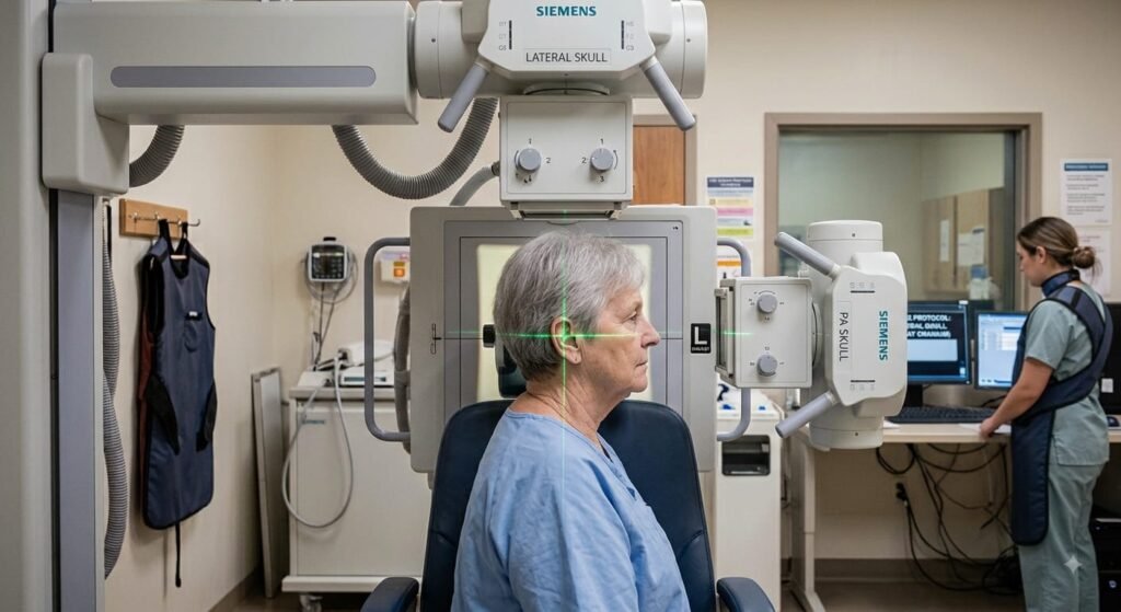
- Erect (Seated/Standing): Patient sits facing the upright Bucky, turning their head and torso laterally so the side of interest rests flat against the receptor.
- Alignment of Reference Lines & Planes:
- Mid-Sagittal Plane (MSP): Must be strictly parallel to the plane of the image receptor. (Verify that the nose and face are not pointed down toward the table or tilted upward).
- Interpupillary Line (IPL): Must be strictly perpendicular to the plane of the image receptor. A small sponge placed under the mandible or nose helps maintain this perpendicularity.
- Infraorbitomeatal Line (IOML): Must be parallel to the long/transverse axis of the image receptor (ensuring no flexed “chin-down” or extended “chin-up” tilt).
4. Central Ray (CR) & Collimation
- Central Ray (CR) Angle: 0⁰ (Perpendicular to the image receptor).
- CR Entry Point: Directed to a point 5 cm (2 inches) superior to the External Auditory Meatus (EAM) (or midway between the glabella and inion). This directly centers the beam over the sella turcica and sphenoid bone.
- Collimation: Four-sided collimation to the outer margins of the skull vault (vertex superiorly, base of skull/C1-C2 inferiorly, and anterior/posterior skin lines).
5. Positioning Errors & Diagnostic Artifacts
| Error Type | Visual Indicator on Radiograph | How to Correct |
| Rotation (Twisting) | Anterior and posterior separation of the bilateral orbital roofs, mandibular rami, and EAMs. | Realign the Mid-Sagittal Plane (MSP) to be strictly parallel to the IR. |
| Tilt (Lateral Leaning) | Superior and inferior separation of the orbital roofs and mandibular angles. | Adjust the Interpupillary Line (IPL) to be strictly perpendicular to the IR. |
| Pitch (Flexion/Extension) | Sella turcica appears angled; occipital base overlaps upper cervical vertebrae excessively. | Realign the IOML parallel to the plane/edge of the IR. |
6. Radiographic Anatomy & Quality Evaluation Criteria
Sella Turcica in True Profile
Anterior and posterior clinoid processes and dorsum sellae visualized without dual-contour distortion.
Superimposed Orbital Roofs
Superimposition of the orbital plates confirms the absence of lateral head tilt (IPL was perpendicular).
Superimposed Mandibular Rami & EAM
Bilateral acoustic canals and rami superimpose directly, verifying no head rotation (MSP was parallel).
Cranial Vault & Sphenoid Sinus
Entire calvarium including vertex to base included; sphenoid sinus clearly aerated beneath the sella.
- Superimposition Criteria:
- True lateral position is confirmed by the complete superimposition of the orbital roofs (plates) and the greater wings of the sphenoid.
- Bilateral mandibular rami and external auditory meatuses (EAMs) superimpose precisely.
- Sella Turcica in Profile: Anterior and posterior clinoid processes, dorsum sellae, and hypophyseal fossa are visualized sharply in profile without dual borders or distortion.
- Bone Detail & Contrast:
- Clear visualization of the diploic space between the inner and outer tables of the cranial vault.
- Clearly defined middle meningeal vascular grooves and cranial sutures (coronal, lambdoid, squamosal).
- Field of Coverage: Entire cranium from the superior vertex to the upper cervical spine (C1-C2 atlantoaxial junction) included without motion blur.
