In diagnostic radiography, controlling the primary X-ray beam is a fundamental requirement for achieving high-contrast images and ensuring strict radiation protection. Unrestricted X-ray beams irradiate tissue outside the clinical area of interest, generating unnecessary Compton scatter radiation that degrades image contrast, increases image fog, and delivers non-diagnostic radiation dose to the patient.
Beam restrictors are specialized beam-shaping devices positioned between the X-ray tube output window and the patient to limit the spatial field size of the primary photon beam.
1. Fundamental Physics: Field Size, Scatter, and Image Quality
When the primary X-ray beam interacts with matter, two primary processes dominate: photoelectric absorption (which provides anatomical contrast) and Compton scattering (which creates unwanted noise).
A. Mechanics of Compton Scatter Generation
The volume of tissue irradiated is directly proportional to the collimated field size:
Irradiated Tissue Volume=Field Area×Patient Thickness
As field size increases, more tissue atoms are exposed to high-energy photons, causing a proportional increase in Compton interactions. These scattered photons emerge at random angles, striking the image receptor from non-primary trajectories and creating uniform optical density (“fog”).
B. Impact on Image Quality and Patient Dose
- Subject Contrast: Restricting the beam reduces scatter radiation reaching the image receptor, significantly enhancing contrast between tissues of similar densities.
- Spatial Resolution: Limiting field size sharpens anatomical margins by reducing scatter-induced edge blur.
- Integral Radiation Dose: Minimizing field size reduces the total energy imparted to the patient, measured via Dose-Area Product (DAP).
2. Classification of Beam Restriction Devices
A. Aperture Diaphragm:
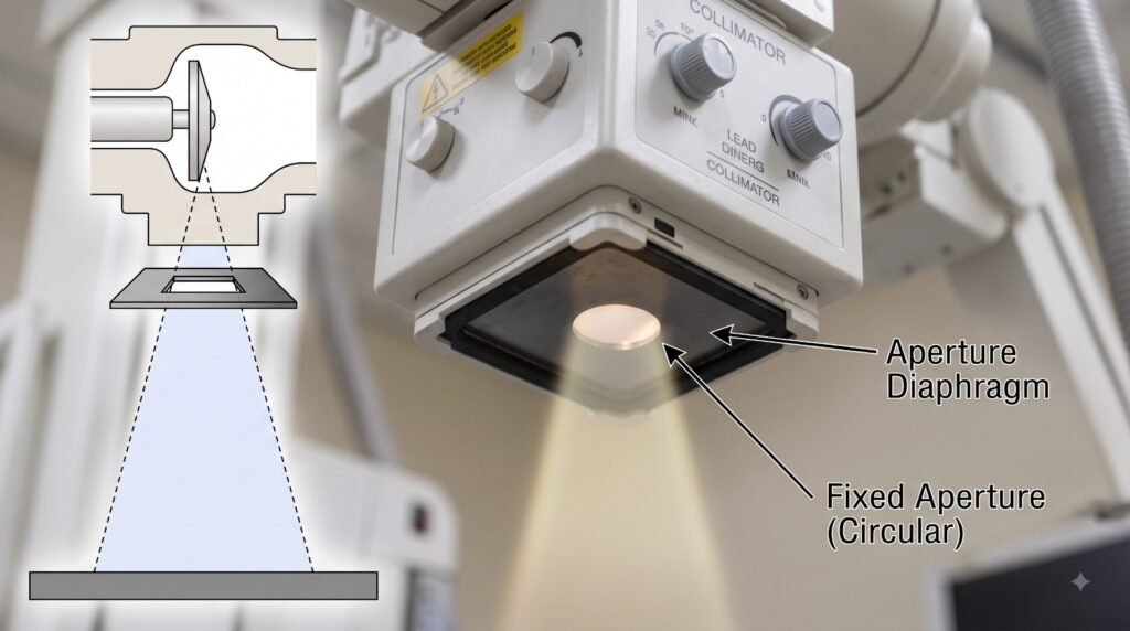
Passes central rays
Blocks Peripheral Rays
Physics and Key Technical Points of Aperture Diaphragms
- Simple Construction: It consists of a flat sheet of lead plate with a fixed cutout opening (aperture) in the center, which can be rectangular, square, or circular in shape.
- Geometric Formula for Field Size: The projected X-ray field size on the image plane determined by the aperture diaphragm is calculated using the following geometric formula:
- Field Size=Aperture Size×SID/Distance from Target to Diaphragm
- (Where SID = Source-to-Image Distance)
- Field Size=Aperture Size×SID/Distance from Target to Diaphragm
- Major Limitation (Geometric Penumbra): Because the lead plate is located extremely close to the focal spot (attached directly to the X-ray tube port), it creates a wide region of edge blur along the periphery of the radiation field, known as Penumbra (Geometric Unsharpness).
- Off-Focus Radiation: Being a single-stage beam restrictor, it cannot completely absorb or block off-focus (extrafocal) radiation. (In modern variable-aperture collimators, first-stage entrance shutters are specifically incorporated to suppress this off-focus radiation).
- Design: The simplest beam-shaping device, consisting of a flat lead sheet with a rectangular, square, or circular cutout.
- Function: Placed directly over the X-ray tube port. The field coverage at a given Source-to-Image Distance (SID) is calculated geometrically using similar triangles:
- Limitation: Located very close to the focal spot, creating a wide geometric penumbra (edge unsharpness) and allowing off-focus radiation to pass through.
B. Cones and Cylinders
Cones vs. Cylinders Schematic Diagram
Allows Central Primary Beam
Blocks Peripheral Rays
Key Comparison
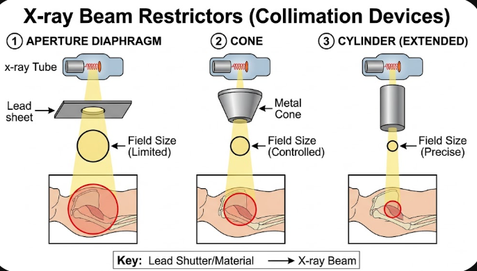
- Extension Cones: Metal tubes that flare outward toward the patient. While better than flat diaphragms, their flared design allows edge penumbra because the bottom opening does not intercept divergent primary rays effectively.
- Extension Cylinders: Straight metal tubes of uniform diameter. They provide superior collimation over cones because the distal opening is farther from the focal spot, cutting off divergent peripheral photons and sharp-focusing the beam boundary.
- Clinical Uses: Dental imaging, sinus studies, and targeted spot radiographing of small anatomical structures (e.g., L5-S1 joint space).
C. Variable-Aperture Light-Localizing Collimator
The standard, most sophisticated beam restriction assembly used in modern diagnostic radiograph units.
3. Detailed Engineering of the Variable-Aperture Collimator
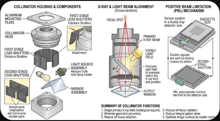
A. Dual-Stage Lead Shutter Assembly
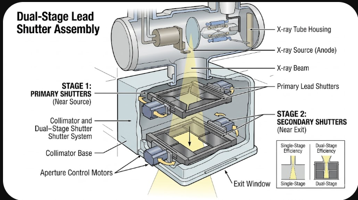
Dual-Stage Shutters Schematic Diagram
Key Engineering Features
- First-Stage (Entrance) Shutters: Mounted inside the upper collimator housing as close as possible to the X-ray tube output window. These lead leaves absorb wide-angle off-focus (extrafocal) photons produced when scattered electrons hit non-target anode components.
- Second-Stage (Exit) Shutters: Comprise two pairs of independently adjustable lead plates (longitudinal and transverse). Moving in opposite directions from the central axis, they shape the beam into rectangular or square fields matching the detector geometry.
B. Optical Light-Localizing Mechanism
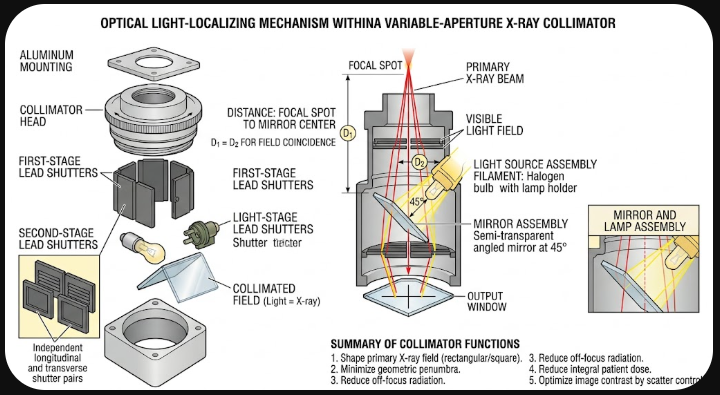
To align the invisible X-ray field with a visual indicator prior to exposure:
- A high-intensity lamp (halogen or LED) is mounted inside the collimator housing.
- A radiolucent silvered mirror is fixed along the central ray path at a precise 45∘ angle.
- Coincidence Calibration: The distance from the focal spot to the center of the mirror must exactly equal the distance from the lamp filament to the center of the mirror (D1=D2). This optical parity ensures the projected light field corresponds precisely with the radiation field at any SID.
C. Automatic Positive Beam Limitation (PBL) System
Modern digital and bucky systems incorporate Positive Beam Limitation (PBL):
- Sensors within the cassette tray detect the dimensions and orientation (portrait/landscape) of the image receptor.
- Drive motors inside the collimator adjust the second-stage lead shutters to limit the radiation field to the cassette size, preventing over-exposure beyond the detector boundary.
4. Comparison of Beam Restrictors
| Device | Edge Penumbra | Off-Focus Suppression | Field Size Adjustability | Primary Clinical Usage |
|---|---|---|---|---|
| Aperture Diaphragm | High | Low | Fixed (Single Size) | Dedicated chest/head units |
| Extension Cone | Moderate | Moderate | Fixed (Flared Field) | Sinus, skull, dental imaging |
| Extension Cylinder | Low | High | Fixed (Circular Field) | High-resolution spot views |
| Variable Collimator | Minimal | Very High | Fully Adjustable (PBL) | General radiography systems |
5. Quality Control and Regulatory Standards
To maintain compliance with diagnostic radiation safety regulations, collimator assemblies undergo periodic Quality Control (QC) evaluations:
- Illuminance Test: The collimator lamp must provide an illumination intensity of at least 160 lux (or 15 foot-candles) at a distance of 100 cm.
- Light Field / X-Ray Field Congruency: The alignment error between the visual light field and the actual radiation beam must not exceed ±2% of the SID along any axis.
- Central Ray Alignment: The perpendicularity of the central ray relative to the image receptor plane must remain within 1∘ of vertical alignment.