Line-Focus Principle in X-Ray Tube: Working Principle, Formula & Diagram

The Line-Focus Principle is a foundational geometric design innovation in diagnostic radiology. It addresses the central paradox of X-ray target design: how to minimize the spatial size of the X-ray source to produce high-resolution medical images while simultaneously maximizing the target area to absorb and dissipate extreme thermal energy.
By slopingly angling the anode target relative to the electron stream, X-ray tube designers decouple the thermal surface area from the effective imaging area, enabling high-power clinical exposures without compromising image detail.
1. The Radiologic Paradox: Resolution vs. Thermal Capacity
In any X-ray imaging system, two opposing requirements compete directly:
- Geometric Spatial Resolution (Image Detail): To minimize geometric unsharpness (also known as the focal spot penumbra, P), the point of X-ray emission must be as small as possible. A smaller focal spot casts sharper shadows of patient anatomy onto the detector:
- Penumbra (P)=f×OID/SOD
- (Where f is focal spot size, OID is Object-to-Image Distance, and SOD is Source-to-Object Distance).
- Thermal Load Limit: More than 99% of the kinetic energy of accelerated electrons striking the target is converted directly into heat, leaving less than 1% converted into useful X-ray radiation. If a high-mA electron beam hits a microscopic focal spot, the local temperature rapidly exceeds tungsten’s melting point (3,422∘C), destroying the target track.
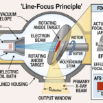
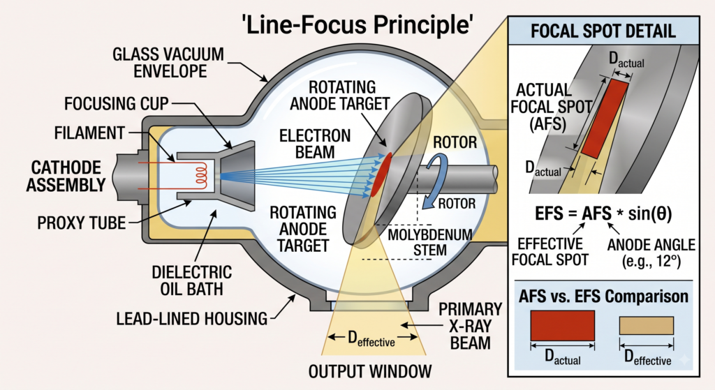
The Line-Focus Principle solves this conflict by using an inclined anode surface to create two distinct focal spot dimensions.
2. Geometry and Definitions: AFS vs. EFS
The core concept relies on angling the target disc face relative to the path of the incoming electron beam:
- Actual Focal Spot (AFS): The true physical area on the tungsten-rhenium target track struck by bombarding electrons. It is rectangular in shape, determined by the length and width of the cathode filament spiral and the focusing cup’s electrostatic field. Because this physical footprint is relatively large, heat is distributed over a wider volume of metal.
- Effective Focal Spot (EFS) / Apparent Focal Spot: The projected area of the X-ray beam when viewed along the central perpendicular axis toward the patient and image detector.
                      Electron Beam (From Cathode)
                                 |   |
                                 |   |
                                 v   v
                         +---------------+  <--- Actual Focal Spot (AFS)
                        /                 \      (Large area for heat absorption)
                       /  Anode Target     \
                      /     Angle (θ)       \
                     +-----------------------+
                                |
                                | Projected Useful Beam
                                v
                     [ Effective Focal Spot ] <--- EFS (Small area for sharp images)
Mathematical Formulation
The geometric relationship governing the Line-Focus Principle is defined by the sine of the anode target angle (θ):
EFS Width=AFS Width×sin(θ)
- As θ decreases (sinθ becomes smaller), the Effective Focal Spot shrinks relative to the Actual Focal Spot.
- For standard diagnostic target angles between 6∘ and 20∘, the effective focal spot is significantly smaller than the physical electron impact zone.
3. Anode Angle Trade-Offs and Clinical Applications
Choosing an anode target angle involves balancing image spatial resolution against total beam coverage.
Practical Applications & Trade-Offs
| Application | Anode Angle Range | Focal Spot Characteristics | Clinical Purpose |
|---|---|---|---|
| Mammography | 6∘ to 10∘ | Micro-focal spot (0.1−0.3 mm) | Ultra-high resolution to detect microcalcifications. |
| General Radiography | 12∘ to 15∘ | Dual focal spot (0.6 mm / 1.2 mm) | Balance between detail and thermal load capacity. |
| High-Power CT / Angiography | 15∘ to 20∘ | Large target track (1.0−1.2 mm) | High heat absorption for rapid, continuous exposures. |
- Mammography (6∘ to 10∘ Target Angle):
- Requires micro-focal spots (0.1 mm to 0.3 mm) to resolve microscopic tissue structures and microcalcifications.
- Small angles generate exceptionally fine spatial resolution, though field size coverage is restricted.
- General Radiography (12∘ to 15∘ Target Angle):
- A 12∘ target angle is the standard industry compromise. It allows a typical dual-filament setup (0.6 mm small focus / 1.2 mm large focus) to cover a standard 35×43 cm image receptor at a standard 100 cm Source-to-Image Distance (SID).
- High-Power CT & Angiography (15∘ to 20∘ Target Angle):
- Designed for maximum heat absorption during rapid, continuous exposures. Larger target angles and wider focal tracks are combined with high-speed anode rotation (10,000 RPM) to withstand immense thermal loads.
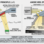
4. Direct Physical By-Product: The Anode Heel Effect
While angling the anode target solves the thermal-resolution conflict, it creates a side effect known as the Anode Heel Effect.
Because X-rays are generated slightly below the surface of the anode target, photons emitted toward the anode side of the tube must pass through a thicker layer of tungsten target material than those emitted toward the cathode side:
- Cathode Side: X-rays experience less self-attenuation → Higher Beam Intensity (∼120%).
- Anode Side: X-rays experience increased self-attenuation → Lower Beam Intensity (∼75%).
Radiographic Technique Adjustment
To compensate for this intensity gradient, radiographers align the cathode side over thicker body anatomy (e.g., placing the cathode over the abdomen or upper femur) and the anode side over thinner anatomy, producing uniform exposure density across the final image.
Summary
The Line-Focus Principle uses target angling (EFS=AFS×sinθ) to deliver sharp diagnostic image resolution while maintaining high thermal load tolerance. It remains a foundational principle of X-ray tube design alongside rotating targets and dielectric oil cooling systems.