

The cathode assembly is the negative terminal within a diagnostic medical X-ray tube. Its fundamental role is to generate a controllable, stable supply of electrons through thermionic emission and electrostatically shape these electrons into a tightly focused beam aimed directly at the positively charged anode target.
Because X-ray production efficiency in diagnostic ranges is under 1% (with over 99% converted into heat), the construction, thermal resistance, and electrodynamics of the cathode assembly directly dictate spatial resolution, exposure output, and overall tube longevity.
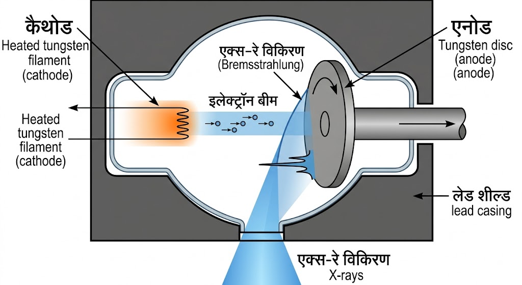
Overall schematic of an X-ray tube showing the cathode and anode components. Source: VectorMine / Getty Images
Anatomical & Structural Breakdown
The modern diagnostic cathode assembly consists of three core engineering sub-units: the filament coils, the focusing cup, and the support/wiring infrastructure.
Top and side views of a dual-filament focusing cup. Source: Radiology Key
1. The Filament Coil
The filament is a small, tightly coiled wire measuring approximately 1 mm to 2 mm in diameter and 7 mm to 15 mm in length.
- Material Physics: Manufactured from thoriated tungsten (tungsten alloyed with 1%−2% Thorium Oxide, ThO2).
- Tungsten (W): Has an extremely high atomic number (Z=74), low vapor pressure, and a melting point of 3,422∘C, preventing premature evaporation at high operating temperatures.
- Thorium Addition: Lowers the work function of tungsten from 4.52 eV down to 2.6 eV, increasing thermionic electron yield at lower operating temperatures.
2. The Focusing Cup
The focusing cup is a metal block containing precision-machined recess cavities where the filament coils rest.
- Material: Constructed from high-melting-point metals with low thermionic emission properties, such as nickel, molybdenum, or stainless steel.
- Electrostatic Principle: Because electrons are negatively charged, an unguided stream diverges due to mutual electrostatic repulsion (Coulomb force). The focusing cup is charged negatively relative to the electron cloud, repelling electrons inward toward the center to form a narrow stream before accelerating across the vacuum gap.
Detailed Electrical Wiring & Circuitry
The cathode assembly relies on two interconnected electrical circuits to produce and accelerate electrons: the Filament Circuit and the High-Voltage Tube Circuit.
                           PRIMARY AC POWER
                                  │
         ┌────────────────────────┴────────────────────────┐
         ▼                                                 ▼
┌───────────────────┐                             ┌───────────────────┐
│ High-Voltage Step-│                             │ Step-Down Filament│
│  Up Transformer   │                             │    Transformer    │
└────────┬──────────┘                             └────────┬──────────┘
         │ (kVp Circuit: 20–150 kV)                        │ (3–6 A, 6–12 V)
         ▼                                                 ▼
┌─────────────────────────────────────────────────────────────────────┐
│                          CATHODE ASSEMBLY                           │
│                                                                     │
│   Common Return Wire ──────────────────────────────────┐            │
│                                                        │            │
│   Small Filament Line ──[ Selector Switch ]───┐        │            │
│                                               ▼        ▼            │
│   Large Filament Line ────────────────────> [ Filament Coil ]      │
│                                                        │            │
│   Focusing Cup Bias Line ──────────────────────────────┘            │
└─────────────────────────────────────────────────────────────────────┘
1. The Filament Circuit (Low Voltage, High Amperage)
The filament circuit provides the energy required to heat the tungsten wire to thermionic emission temperatures (>2,200∘C).
- Step-Down Transformer: Standard line voltage (220 V−480 V) is stepped down to low operating voltages (6 V−12 V) while increasing current to high levels (3 A−6 A).
- Current Control & mA Station: Small changes in filament current (If) lead to large changes in electron output and tube current (It). Precision variable resistors (rheostats) or solid-state frequency regulators adjust current to select the desired exposure setting (50 mA,100 mA,500 mA, etc.).
- Standby Current vs. Exposure Ramping: To prevent thermal shock, a low standby current keeps the filament warm when the system is idle. Depressing the exposure button ramps up the filament current to full operational temperature within milliseconds.
2. The High-Voltage Tube Circuit (kVp Circuit)
The high-voltage circuit provides the potential difference across the tube gap.
- Step-Up Transformer & Rectifiers: Step-up transformers increase incoming voltage to high values (20 kVp−150 kVp). Direct current (DC) conversion via silicon rectifiers ensures the cathode remains negative and the anode remains positive.
- Electron Acceleration: When kVp is applied, the potential difference creates a high-intensity electric field. The emitted electron cloud is accelerated from the cathode toward the target anode at velocities up to half the speed of light (0.5c).
3. Cathode Wiring Architecture & Focal Spot Switching
Standard dual-focus cathode assemblies use a three-wire or four-wire lead system connected through a high-voltage receptacle:
- Common Return Lead: Completes the circuit loop back through the filament transformer for both filaments.
- Small Filament Power Lead: Connects through a relay switch to energize the small filament coil.
- Large Filament Power Lead: Connects through a relay switch to energize the large filament coil.
- Focusing Cup Connection: Tied directly to the filament circuit or connected to an independent bias voltage circuit.
Dual-Focus Systems & Focal Spot Dynamics
Most general diagnostic X-ray tubes feature a dual-focus cathode assembly, which houses two filaments of differing sizes placed side-by-side or end-to-end inside the focusing cup.
                          Dual-Focus Cathode Block
                   ┌────────────────────────────────────┐
                   │    ┌─────────┐      ┌───────────┐  │
                   │    │ Small   │      │ Large     │  │
                   │    │ Filament│      │ Filament  │  │
                   │    └─────────┘      └───────────┘  │
                   └──────────────────┬─────────────────┘
                                      │
                 ┌────────────────────┴────────────────────┐
                 ▼                                         ▼
   [ Small Focal Spot ]                      [ Large Focal Spot ]
   • High spatial resolution                 • High thermal loading capacity
   • Low mA limits (up to 200 mA)            • High mA capacity (up to 1000+ mA)
   • Extremity & pediatric imaging           • Chest, abdomen, bariatric imaging
| Parameter | Small Filament / Focal Spot | Large Filament / Focal Spot |
|---|---|---|
| Nominal Size | 0.1 mm−0.6 mm | 1.0 mm−1.2 mm |
| Spatial Resolution | High detail (minimal geometric unsharpness) | Moderate detail |
| Heat Loading Capacity | Low (risk of filament damage at high mA) | High (distributes heat over larger target area) |
| Clinical Uses | Small bones, extremities, mammography | Thick body parts (chest, pelvis, abdomen) |
Physical Phenomena & Governing Principles
1. Thermionic Emission
When current flows through the filament, electrical resistance generates heat energy (P=I2R). Above 2,200∘C, outer-shell electrons absorb enough kinetic energy to overcome the metallic binding forces (work function) and break free from the tungsten lattice.
2. Space Charge Effect & Space Charge Limitation
At low tube voltages (<40 kVp), electrons boiled off the filament hover immediately in front of it, forming a localized cloud called the space charge.
Because these electrons carry negative charges, they exert a repulsive force back onto the filament surface. This counter-force prevents additional electrons from escaping—a state known as space charge limited operation.
Filament Heating ──> Electron Emission ──> Negative Cloud (Space Charge) ──> Repels New Electrons
3. Saturation Current (Temperature-Limited Region)
As applied tube voltage (kVp) increases, the electrostatic attraction from the positive anode sweeps electrons across the vacuum gap faster than they can accumulate.
Once kVp reaches a high enough level (typically >40 kVp in standard diagnostic systems), all emitted electrons are driven toward the target immediately. Beyond this point—known as the saturation point—further increases in kVp will not increase tube current (mA). Tube current is then strictly temperature-limited and can only be increased by raising the filament current.
Advanced Cathode Technologies: Grid-Controlled Tubes
In specialized applications such as high-speed angiography, pulsed fluoroscopy, and CT scanning, exposure times must be rapidly pulsed (hundreds of times per second). Standard X-ray generators cannot ramp kVp up and down quickly enough to achieve this.
A grid-controlled X-ray tube modifies the focusing cup to act as a fast electronic switch:
- Exposure On: The focusing cup is kept at the same potential as the filament, allowing electrons to flow across to the anode.
- Exposure Off: A sharp negative bias voltage (around −2,000 V) is applied to the focusing cup relative to the filament. This strong negative field completely blocks the electron cloud from leaving the cup, instantly pinching off tube current without turning off the high-voltage generator.
Filament Degradation & Failure Modes
Because the cathode is subjected to extreme thermal cycles, it is a primary source of X-ray tube failure over time:
- Tungsten Vaporization & Evaporation: Over thousands of exposures, tungsten atoms gradually evaporate from the filament wire. This leads to two issues:
- Thinning of the Filament Wire: Thinner wire increases electrical resistance, causing the filament to run hotter and emit more electrons at a given current setting over time (filament aging).
- Tungsten Arcing (Arking): Vaporized tungsten deposits as a metallic film on the inside glass or metal envelope, creating an electrical pathway that can cause high-voltage arcing and rupture the tube.
- Filament Burnout: Continued thinning eventually causes the wire to snap under thermal stress, resulting in open-circuit tube failure.
- Pitting & Deformation: Thermal cycles can warp the physical shape of the filament coil within the cup, distorting the focal spot symmetry and degrading spatial resolution.
