

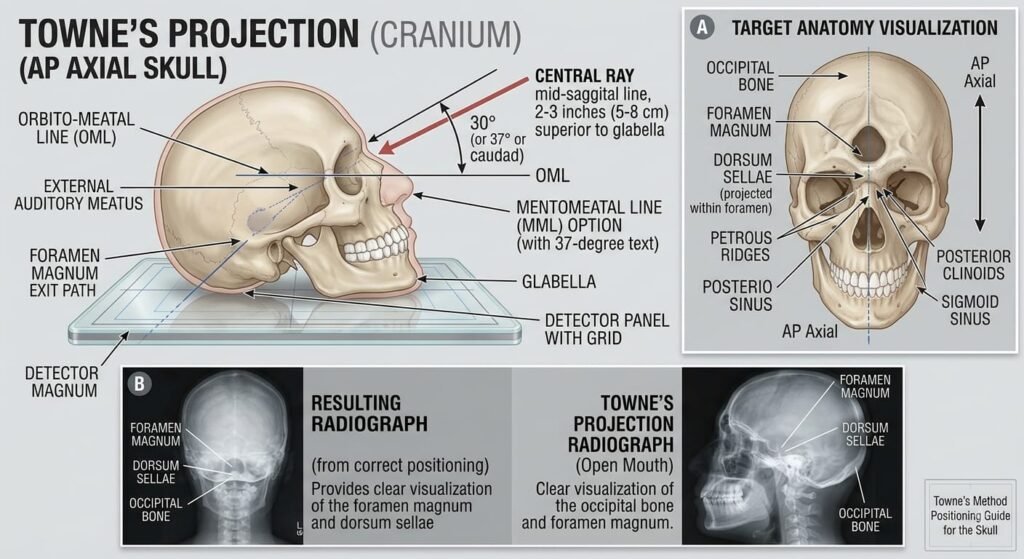
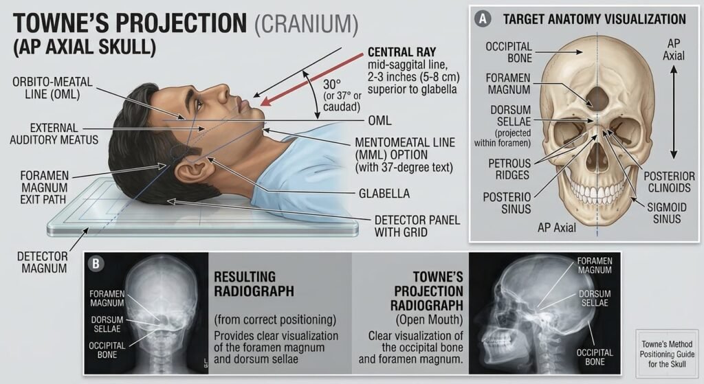
The Towne’s Projection (AP Axial Skull) is an essential specialized cranial view designed to project the dense anterior facial bones and frontal structures away, providing an unobstructed, symmetrical view of the occipital bone, foramen magnum, petrous pyramids, dorsum sellae, and posterior clinoid processes.
1. Clinical Indications & Contraindications
Detailed Indications:
- Occipital Bone Trauma & Pathology: Detection of occipital bone fractures (linear, depressed, or basal fractures) and evaluation of cortical thinning or calvarial lesions.
- Posterior Fossa Assessment: Evaluation of the posterior cranial fossa, internal acoustic meati (IAM), and acoustic neuroma (vestibular schwannoma) causing canal widening.
- Sellar & Parasellar Evaluation: Direct visualization of the dorsum sellae and posterior clinoid processes projected inside the shadow of the foramen magnum.
- Petrous Pyramids & Temporal Bone Pathologies: Assessment of petrous apex symmetry, mastoid air cells, labyrinthitis, and cholesteatoma.
- Condylar Process & TMJ Trauma: Evaluation of high subcondylar fractures and medial displacement of the mandibular condyles.
- Metabolic & Neoplastic Disorders: Paget’s disease involving the skull base (basilar invagination), Multiple Myeloma, and osteolytic metastases in the occipital region.
Contraindications & Limitations:
- Unstable Cervical Spine Trauma: Never forcefully flex the neck to achieve the standard perpendicular Orbitomeatal Line (OML). Use the Infraorbitomeatal Line (IOML) baseline instead and increase the caudal tube angle.
- Severe Anterior Facial / Orbital Evaluation (Limitation): This view distorts and projects the anterior orbital rims, facial bones, and frontal sinuses downward, making it unsuited for facial bone or anterior orbit trauma.
2. Technical Factors
| Parameter | Recommended Specification | Radiographic Rationale |
| Source-to-Image Distance (SID) | 100 to 115 cm (40 to 44 inches) | Standard distance; account for tube tilt to avoid grid cut-off |
| Image Receptor (IR) | 24 × 30 cm (10×12 inches) | Longitudinal / Portrait orientation |
| Grid Ratio | 8: 1 to 12: 1Esfocused grid | Essential to absorb scatter from thick occipital bone |
| Tube Potential (kVp) | 75 – 85 kVp | High penetration needed to pass obliquely through the skull base |
| mAs Range | 28 – 40 mAs | Slightly higher exposure than 0⁰ AP due to beam angulation path length |
| Focal Spot | Small (0.6 mm) | High spatial resolution for fine margins inside the foramen magnum |
| Breathing | Suspended respiration | Eliminates respiratory motion blur |
3. Step-by-Step Patient & Part Positioning
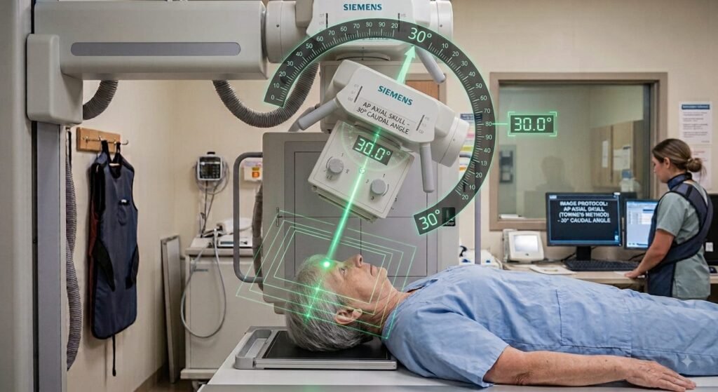
30° Caudad (OML ⟂) OR 37° Caudad (IOML ⟂)
Enters 2.5″ (6.5 cm) Superior to Glabella ➔ Exits Foramen Magnum
(Standard protocol paired with 30° caudal tilt)
(Requires 37° caudal tilt to compensate)
(Aligned with vertical midline to prevent rotation)
Top of cassette placed at the level of the cranial vertex
Entry Point (2.5″ Above Glabella)
Directs the angled beam through the hairline/forehead to pass directly through the foramen magnum and base of skull.
OML vs. IOML Baseline Selection
Use 30° caudad with OML perpendicular; if the patient cannot tuck the chin sufficiently, align IOML perpendicular and angle 37° caudad.
MSP Perpendicular (90°)
Ensures zero cranial rotation so the petrous pyramids and posterior clinoid processes project symmetrically.
Foramen Magnum Projection
Proper angle placement projects the dorsum sellae and posterior clinoids directly within the shadow of the foramen magnum.
- Patient Preparation: Remove all metallic and radiopaque objects (hairpins, clips, spectacles, earrings, necklaces, dentures, and hearing aids).
- General Posture Options:
- Supine (Standard): Patient lies supine on the radiographic table with shoulders leveled.
- Erect (Alternative): Patient seated erect against the vertical Bucky with the back of the head (occiput) resting against the receptor.
- Alignment of Reference Lines & Planes:
- Mid-Sagittal Plane (MSP): Align MSP strictly perpendicular to the midline of the grid/table. Ensure zero head rotation or lateral tilt.
- Orbitomeatal Line (OML): Gently depress the chin so that the OML is strictly perpendicular to the image receptor surface.
- Trauma / Stiff Neck Alternative (IOML): If the patient cannot tuck the chin and only the Infraorbitomeatal Line (IOML) is perpendicular, adjust the central ray angle accordingly.
- Interpupillary Line (IPL): Must be strictly parallel to the IR surface to prevent lateral cranial tilt.
4. Central Ray (CR) & Collimation
- CR Tube Angulation:
- 30⁰ Caudad when the OML is perpendicular to the IR.
- 37⁰ Caudad when the IOML is perpendicular to the IR (compensates for the 7⁰ anatomical difference).
- CR Entry Point: Directed through the midline, entering approximately 6.5 cm (2.5 inches) superior to the glabella (passing through the level of the external auditory meatus) and exiting at the foramen magnum.
- IR Alignment: The upper border of the IR must be positioned approximately 5 cm (2 inches) above the cranial vertex to prevent clipping of the elongated occipital bone due to caudal beam divergence.
- Collimation: Four-sided collimation to the outer skin margins of the skull vault.
5. Positioning Errors & How to Fix Them
| Error Type | Radiographic Appearance | Cause & Correction |
| Under-Angulation (< 30° / Insufficient Chin Tuck) | The dorsum sellae is projected superior to the foramen magnum, superimposing over the occipital bone. | Increase the caudal tube angle or tuck the chin further to bring OML perpendicular. |
| Over-Angulation (> 30° / Excessive Chin Tuck) | The posterior arch of the atlas (C1) is projected inside the foramen magnum, obscuring the dorsum sellae. | Decrease the caudal tube angle or slightly extend the chin. |
| Rotation (Twisting) | Asymmetric distance from the lateral margin of foramen magnum to lateral skull borders; uneven petrous ridges. | Ensure the MSP is perfectly perpendicular to the IR midline. |
| Lateral Tilt | Petrous ridges and internal acoustic canals are tilted and not on the same horizontal plane. | Realign the IPL parallel to the IR surface. |
6. Radiographic Anatomy & Quality Evaluation Criteria
Dorsum Sellae in Foramen Magnum
Dorsum sellae and posterior clinoid processes project cleanly within the radiolucent oval of the foramen magnum.
Internal Acoustic Meatuses (IAMs)
Bilateral acoustic canals demonstrated symmetrically within the upper borders of the petrous temporal ridges.
Occipital Squama Visualization
Broad area of the occipital bone is projected free of superimposition, showing intact cortical margins.
Petrous Ridge Symmetry
Equal distance from the lateral borders of the foramen magnum to the lateral cranial cortex confirms zero rotation.
- Structures Inside the Foramen Magnum: Correct angulation is verified when the dorsum sellae and posterior clinoid processes are clearly projected within the shadow of the foramen magnum.
- Symmetry:
- Symmetrical petrous pyramids on either side of the midline.
- Equal distance from the lateral margins of the foramen magnum to the outer calvarial edges.
- Visualized Anatomy:
- Occipital bone in its entirety from vertex to foramen magnum.
- Petrous ridges, mastoid air cells, internal acoustic canals (IAM), and posterior parietal bones.
- Sharpness & Exposure: Clear cortical outlines of the occipital bone with no movement artifacts and no grid cut-off lines.
