
Anode Heel Effect in X-Ray Tube: Physics, Factors & Clinical Applications

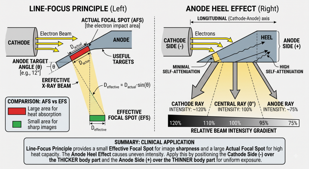
The Anode Heel Effect is an inherent physical phenomenon in diagnostic X-ray tube assemblies. It refers to the variation in radiation intensity along the longitudinal (anode-to-cathode) axis of the primary X-ray beam. Specifically, the beam intensity is significantly higher on the cathode side than on the anode side.
While the Line-Focus Principle uses a sloped target to achieve a small effective focal spot without overheating the anode, the Anode Heel Effect is the direct physical trade-off of that geometry. Understanding this gradient is vital for optimizing radiographic image quality, reducing exposure artifacts, and minimizing patient radiation dose.
1. Fundamental Mechanism & Physical Origin
X-rays are not produced solely on the micro-surface of the tungsten target. When high-velocity electrons from the cathode filament strike the anode track, they penetrate a few micrometers deep into the target material before undergoing Bremsstrahlung or Characteristic interactions.
Because the anode target face is set at an incline (the anode angle, θ):
- Cathode-Directed Photons: X-rays emitted toward the cathode side exit the target surface through a minimal thickness of tungsten. They experience minimal self-attenuation.
- Anode-Directed Photons: X-rays emitted toward the anode side must travel through a thicker path of tungsten target material (the “heel” of the anode) to escape the metal surface.
Cathode Side
• Short path through target
• High self-attenuation (Low)
• High Intensity
Central Ray
Standard Reference Ray
Anode Side
• Long path through target
• High self-attenuation
• Low Intensity
Because tungsten has a very high atomic number (Z=74), this extra distance acts as an inherent filter. The anode material attenuates low-energy photons and reduces total photon flux on the anode side of the field.
2. Relative Intensity Distribution Across the Field
In a standard diagnostic X-ray exposure operating at a 100 cm Source-to-Image Distance (SID), beam intensity across a 35×43 cm field varies by up to 45% from end to end:
| Position across Collimation Field | Relative Intensity | Physical Mechanism |
|---|---|---|
| Far Cathode Side | 120% to 125% | Minimal self-attenuation; maximum photon flux. |
| Central Ray (0∘ Axis) | 100% | Calibrated reference intensity output. |
| Far Anode Side | 75% to 80% | Maximum self-attenuation through the anode heel. |
3. Factors Influencing the Severity of the Heel Effect
Three key operational and geometric factors determine how severe the intensity gradient will be:
A. Anode Target Angle (θ)
- Inverse Relationship: Smaller target angles increase the severity of the heel effect.
- Physics: A steep target angle (e.g., 6∘ to 10∘ ) requires photons traveling toward the anode side to traverse a longer path of tungsten relative to a wider angle (e.g., 15∘ to 20∘ ).
B. Source-to-Image Receptor Distance (SID)
- Inverse Relationship: Shorter SIDs worsen the perceived heel effect on the image.
- Physics: At a short SID (e.g., 75 cm), the image receptor captures the outer edges of the divergent beam where intensity extremes (75% vs 120%) exist. At a long SID (e.g., 180 cm), only the more uniform central region of the beam hits the detector.
C. Field Size (Collimation Area)
- Direct Relationship: Larger collimation field sizes expose more of the heel effect gradient.
- Physics: Tight collimation clips off the peripheral, non-uniform edges of the beam, isolating the central, uniform ray.
Factors Increasing Anode Heel Effect:
- Decreased Anode Angle (θ ↓)
- Decreased Source-to-Image Distance (SID ↓)
- Increased Field Size / Open Collimation (Field Size ↑)
4. Clinical Applications and Positioning Strategies
Radiographers leverage the Anode Heel Effect to balance density/exposure on body parts with non-uniform thickness. By aligning the cathode side over the thicker anatomy and the anode side over the thinner anatomy, the final radiograph achieves uniform optical density.
Cathode (-) Side (Thicker Anatomy) ------------> Anode (+) Side (Thinner Anatomy)
Common Clinical Exams Relying on Heel Effect Alignment:
- Thoracic Spine (AP View): Position the cathode end over the lower thoracic vertebrae (thicker region near the abdomen) and the anode end over the upper thoracic vertebrae (thinner neck/chest region).
- Femur / Lower Extremity: Position the cathode end over the proximal femur (hip/thigh) and the anode end over the distal femur (knee joint).
- Abdomen (AP View): Position the cathode over the upper abdomen/diaphragm and the anode over the lower pelvic region.
- Mammography: Specialized tubes position the cathode over the thick chest wall base and the anode over the thinner anterior nipple region to balance tissue exposure.
Summary
The Anode Heel Effect is an unavoidable consequence of using sloped targets to manage heat via the Line-Focus Principle. While it introduces a ∼45% intensity variation across the longitudinal axis of the beam, understanding the governing variables (θ, SID, field size) allows medical imaging professionals to utilize this intensity gradient for improved anatomical exposure uniformity and patient dose protection.
